MEMS gyroscope accurate installation reference component and installation method thereof

A technology of installation reference and gyroscope, which is applied to gyroscope/steering sensing equipment, gyro effect for speed measurement, instrument and other directions, can solve the problems of poor anti-interference ability, difficult to control precision, poor stability, etc., to improve installation accuracy, Improved installation accuracy and good stability

Inactive Publication Date: 2008-01-23
BEIHANG UNIV
View PDF0 Cites 30 Cited by
  • Summary
  • Abstract
  • Description
  • Claims
  • Application Information

AI Technical Summary

Problems solved by technology

[0007] (1) The micro MEMS gyroscope relies on the circuit board to ensure the direction of the horizontal sensitive axis, and the circuit board is generally a plastic substrate, its stiffness, strength, hardness and other indicators are very low, easy to deform, poor stability, low vibration mode, and easy to be affected by The influence of the external environment and poor anti-interference ability greatly reduce the assembly accuracy of the micro MEMS gyroscope body and other components
[0008] (2) The flatness, smoothness and other indicators of the surface of the circuit board are far lower than the general metal mounting surface. If the circuit board with core sensitive components is directly installed on the bracket of the inertial measurement unit, these factors will directly affect the micro MEMS. The size of the vertical def

Method used


Image

  • MEMS gyroscope accurate installation reference component and installation method thereof
  • MEMS gyroscope accurate installation reference component and installation method thereof
  • MEMS gyroscope accurate installation reference component and installation method thereof

Examples


Embodiment Construction

[0033] The present invention takes the micro-MEMS gyroscope and the quartz MEMS gyroscope LCG50 produced by BEI Company as an example, and designs a precision-installed reference body assembly.

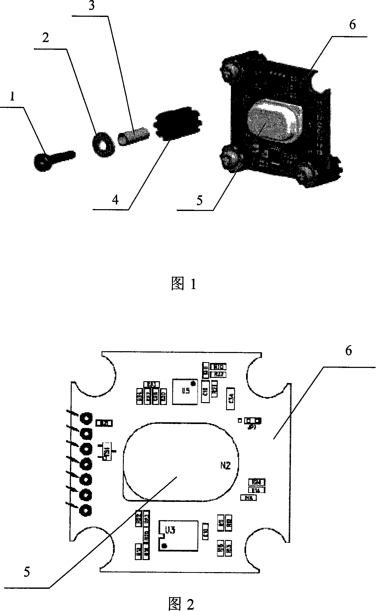
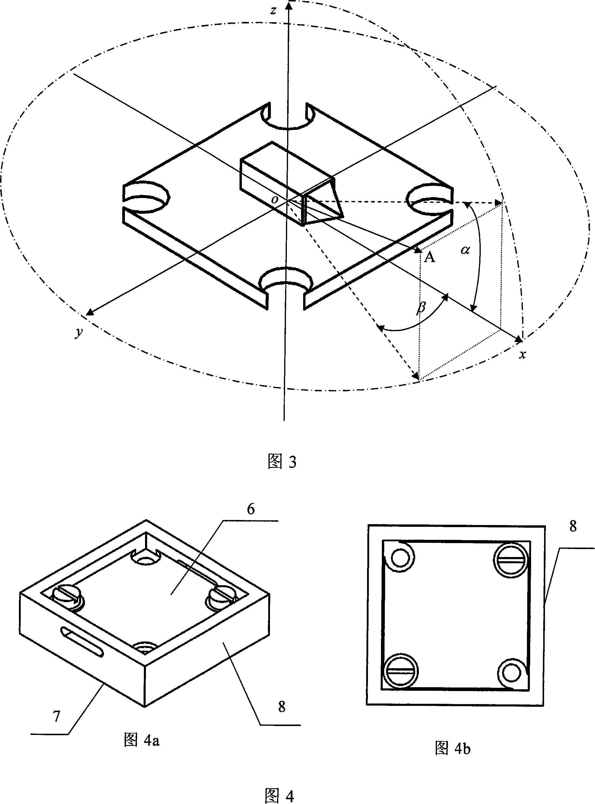
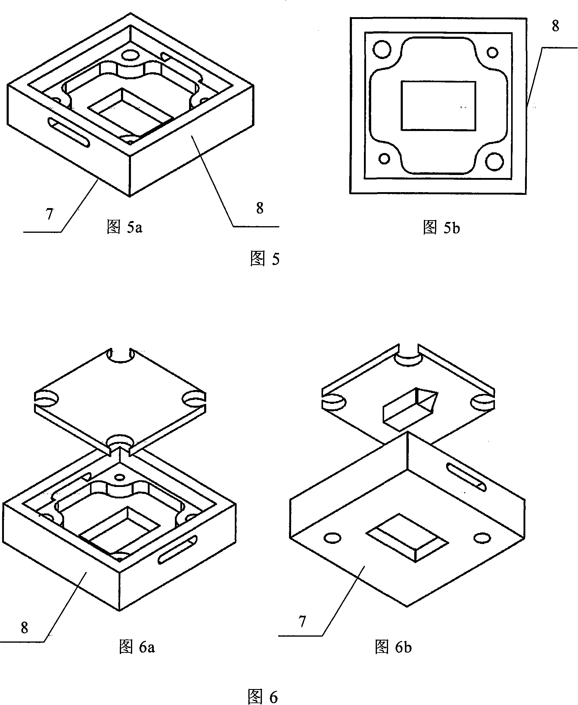
[0034] The assembly diagram of the precise installation reference body assembly of LCG50 is shown in Figure 4, including the precision installation reference body and the micro MEMS vibrating gyroscope body at the level of the sensitive axis. Its precision installation datum body is shown in Figure 5, the main body is a cuboid with a smooth outer surface, including a first datum plane, a second datum plane and an inner concave space. The inner recessed space is recessed from the upper surface to the inside, and the shape is designed according to the external dimensions of the LCG50 gyroscope body, so that the LCG50 gyroscope body is embedded in the inner recessed space of the precision installation reference body, and the LCG50 gyroscope body and the precision installation reference bo...


PUM


Abstract

The invention provides an assembly of the reference body for the precision installation of a MEMS gyrometer and the installing method. The assembly comprises a precision installation reference body and a mini MEMS vibration gryometer body with a horizontal sensitive-axis that is inserted into the concave space in the reference body. The reference body is made of material with good assembling performance and secondary machining performance. The assembly is connected with a carrier through a first reference face and a second reference face. At installation, firs the preliminary shape of the reference body is machined, and the gyrometer is mounted, then the out-of-spec angle of the input axis of the gyro is measured, the installation drift angle is calculated; then the reference face of the reference body is corrected based on the drift angle so that the drift angle approaches to zero. The invention takes use of the excellent assembling and secondary machining performance of the material from which the reference body is made, improves the installation accuracy of the gyro by machining and correction, is applicable for mini gyrometers with horizontal sensitive-axis installed by circuit board, especially for mini MEMS vibration gyrometer in inertia measuring units in small carriers.

Description

technical field [0001] The invention belongs to the technical field of navigation, guidance and control, in particular to a MEMS gyroscope precision installation reference body assembly and an installation method thereof, which are suitable for low-cost, micro-miniature MEMS vibrating gyroscopes with various sensitive axis levels. Background technique [0002] Inertial measurement unit is a very important device in navigation, guidance and control system. It consists of three gyroscopes and three accelerometers. According to the requirements of the inertial navigation principle, the sensitive axes of the three gyroscopes are required to be perpendicular to each other in space and parallel to the corresponding three carrier coordinate axes. The inertial measurement unit does not rely on external information, does not radiate energy to the outside world, and is not easily disturbed. This unique advantage makes it a widely used main carrier, especially in the fields of aerospac...

Claims


Application Information

Patent Timeline
IPC IPC(8): G01C19/56G01C21/18G01C19/5783
Inventor 房建成张海鹏陶冶冯浩楠秦杰蒋颜伟
Owner BEIHANG UNIV
Why Eureka
Try Eureka