Spraying degasser

A degassing device, degassing container technology, applied in the direction of measuring devices, instruments, scientific instruments, etc., can solve problems such as poor reproducibility, excessive water vapor, manual operation, etc., achieve accurate and reliable measurement methods, simple design and operation, and solve Effects of moisture problems

Inactive Publication Date: 2010-08-25
SHANGHAI GASOLINEEUM & CHEM EQUIP +1
View PDF2 Cites 0 Cited by
  • Summary
  • Abstract
  • Description
  • Claims
  • Application Information

AI Technical Summary

Problems solved by technology

[0003] Many patents related to degassing technology have been applied for and published, but most of the degassing devices cannot realize automatic measurement, such as the utility model patent of the group, the patent number is ZL02217830. "It uses vacuum, stirring and heating technology. Although the degassing efficiency is very high, it is manually operated. Currently, the device that realizes continuous automatic degassing, such as the utility model patent applied by the Fujian Provincial Seismological Bureau, the patent number is ZL02228947.X , the patent name is "Dissolved Gas Quantitative Degassing Device", which includes a diffuser and a bubbling degassing circulation line, which can prepare a quantitative volume of gaseous samples of related dissolved gas components that establish a dissolution equilibrium relationship with the measured water sample
Although the balanced dissolution degassing system and stirring heating system developed at present can achieve the purpose of automatic degassing monitoring, they have the disadvantages of too much water vapor during the heating process, it is difficult to dry completely, and there are many valves, complex structure, and complicated operation.
Membrane degassing devices have the following disadvantages: some degassing membranes take a long time to degas, and some degassing membranes are difficult to control the separation of water vapor, so the reproducibility of the experimental process is poor. The membrane is relatively easy to pollute, and the degassing membrane is cleaned or replaced at regular intervals, and the device needs frequent maintenance. There are also many tests on other systems such as automatic dissolution and degassing of underground fluids, but there are also complex structures and water vapor generated after the heating process, etc. question

Method used


Image

  • Spraying degasser
  • Spraying degasser

Examples


Embodiment

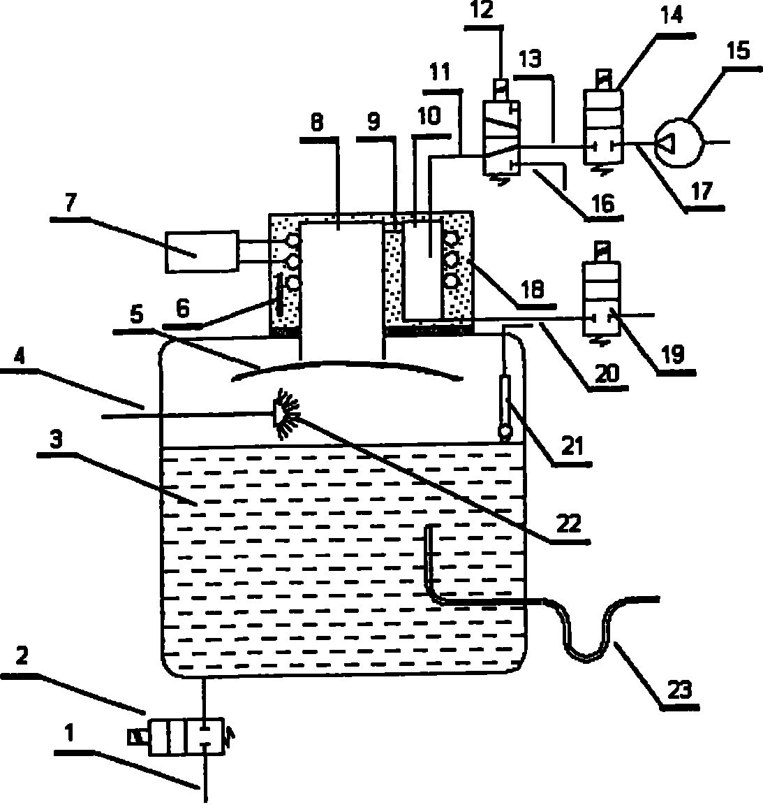
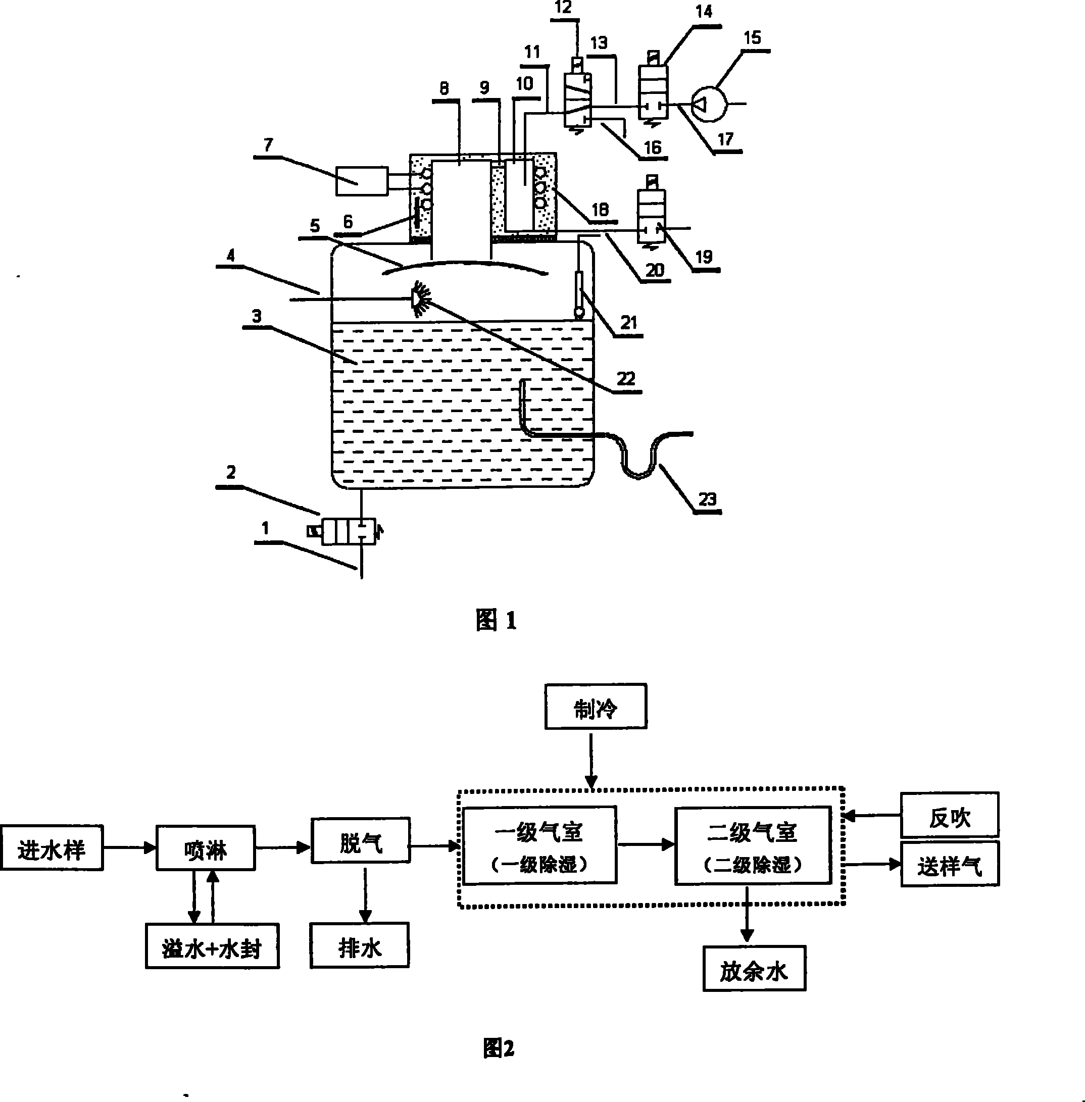
[0021] As shown in Figure 1, it is a schematic structural view of a spray degassing device, said a kind of spraying degassing device consists of a drain pipe 1, a solenoid valve A 2, a degassing container 3, an inlet pipe 4, a baffle plate 5, Temperature control system 6, refrigeration system 7, primary air chamber 8, connecting pipe A 9, secondary air chamber 10, connecting pipe B 11, two-position three-way solenoid valve A 12, connecting pipe C 13, solenoid valve B 14, Reverse blowing pump 15, air pipe 16, connecting pipe D 17, intercooled low-temperature metal test bath 18, two-position three-way solenoid valve B 19, residual water pipe 20, liquid level sensor 21, nozzle 22, and overflow pipe 23.

[0022] The drain pipe 1 is installed at the bottom of the degassing container 3 through the solenoid valve A2, and the overflow pipe 23 is installed on one side of the lower end of the degassing container 3. The outlet of the overflow pipe 23 is U-shaped, and its inner diameter is...


PUM


Abstract

The invention relates to a spraying degassing arrangement, which is characterized in that, a water drain pipe is located at the bottom of a degassing container through a solenoid valve A; a water overflowing pipe is located at one side at the lower end of the degassing container; a level sensor and a nozzle are located at the upper part in the degassing container; the nozzle is connected with a water-in pipe; a baffle is located at the top in the degassing container; an indirectly cooled low-temperature test bath is located above the degassing container; a stage-I air chamber and a stage-II air chamber are arranged in the indirectly cooled low-temperature test bath; the stage-I air chamber is communicated with the degassing container, and is located above the baffle; a temperature controlling system in the indirectly cooled low-temperature test bath is connected with a refrigerating system outside the indirectly cooled low-temperature test bath; the upper end of the stage-I air chamber and that of the stage-II air chamber are connected through a connection pipe A; the upper end of the degassing container is provided with a pipe for draining residual water, and is connected with the 2-position 3-way solenoid valve A through a connection pipe B; one way of the solenoid valve A is connected with a back blowing pump through a connection pipe C, another way of the solenoid valve A is connected with a gas delivery pipe. The invention can be interconnected with an automatic gas-phase chromatograph so as to carry out on line inspection.

Description

technical field [0001] The patent of the present invention relates to a spray degassing device, in particular to a set of degassing devices used in early earthquake prediction using automatic gas chromatography and sensors to detect gas components in underground fluids, belonging to the technical field of degassing devices. Background technique [0002] The dynamic observation of underground fluid has been one of the main precursory means for early earthquake prediction at home and abroad for many years. Certain dissolved gas components of underground fluid, such as hydrogen, oxygen, helium, argon, carbon dioxide, nitrogen, methane, hydrogen sulfide, etc. An important part of the early omen. The instruments for detecting these dissolved gases, such as gas chromatographs and sensors, are more suitable monitoring methods. How to convert the dissolved gases in the underground fluid into gaseous samples and continuously and automatically send the gaseous samples to analytical in...

Claims


Application Information

Patent Timeline
Patent Type & Authority Patents(China)
IPC IPC(8): G01N30/06G01N1/34
Inventor 顾冰陈志敏曹兆钧谢红霞
Owner SHANGHAI GASOLINEEUM & CHEM EQUIP
Why Eureka
Try Eureka