
Substrate processing with rapid temperature gradient control

A substrate and substrate support technology, which is applied in semiconductor/solid-state device manufacturing, electrical components, circuits, etc., can solve problems such as non-uniform processing, and achieve the effect of rapid temperature control

Active Publication Date: 2008-01-23
APPLIED MATERIALS INC
View PDF1 Cites 37 Cited by
  • Summary
  • Abstract
  • Description
  • Claims
  • Application Information

AI Technical Summary

Problems solved by technology

Non-uniform heat loads in the chamber may also cause non-uniform processing

Method used


Image

  • Substrate processing with rapid temperature gradient control
  • Substrate processing with rapid temperature gradient control
  • Substrate processing with rapid temperature gradient control

Examples


Embodiment Construction

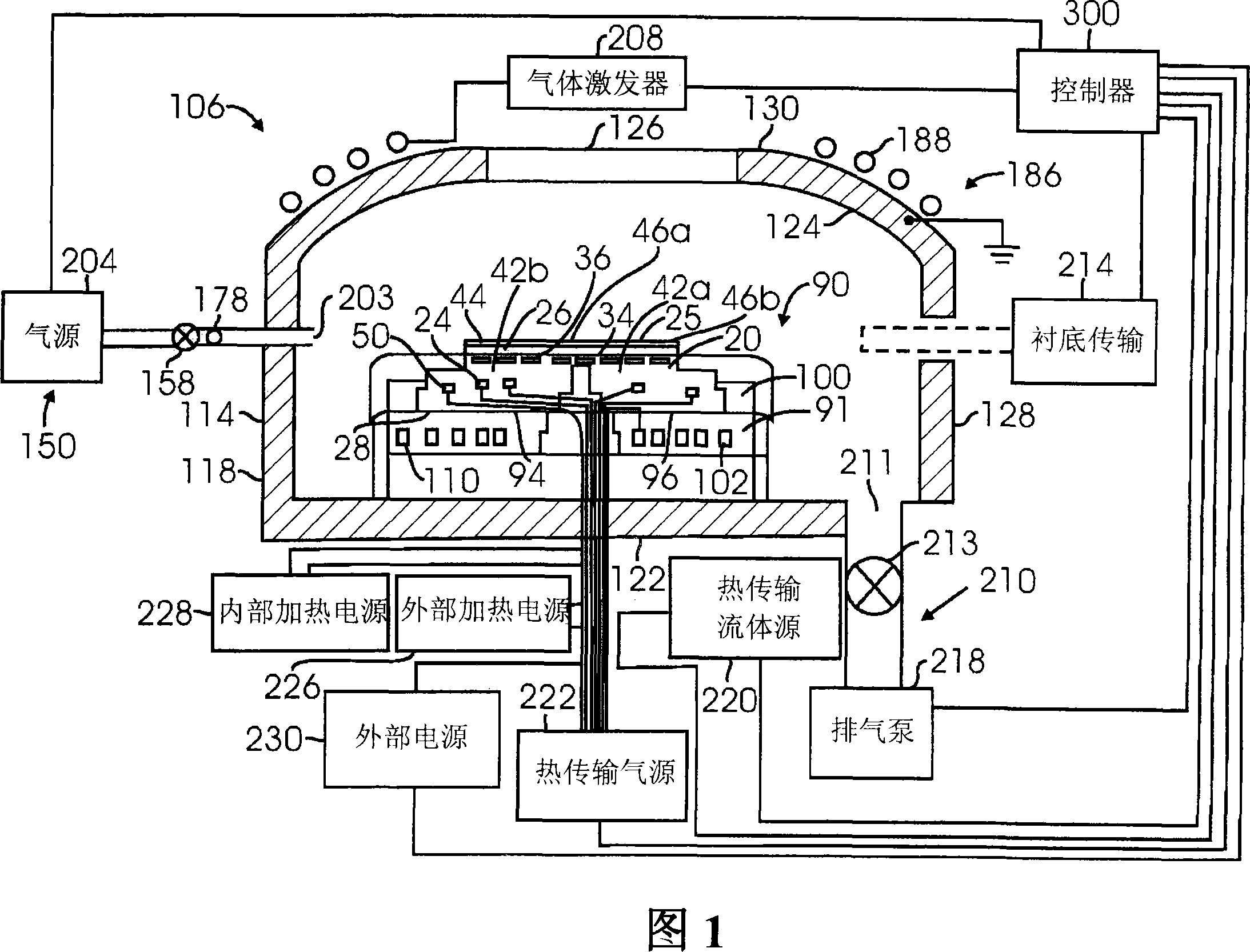
[0025] An exemplary scheme of the chamber 106 capable of etching the substrate 25 is schematically shown in FIG. 1. Chamber 106 represents Decoupled Plasma Source (DPS TM ) Chamber, which is an inductively coupled plasma etching chamber provided by Applied Materials Inc. of Santa Clara, California. The DPS chamber 106 can be used in the CENTURA(R) Integrated Processing System, which is provided by Applied Materials Inc. of Santa Clara, California. However, other process chambers can also be used in combination with the present invention, including, for example, a capacitively coupled parallel plate chamber, an electromagnetically enhanced ion etching chamber, an inductively coupled plasma etching chamber of different designs, and a deposition chamber. Although the equipment and process of the present invention are preferably used in a DPS chamber, the present invention provides the chamber only for describing the present invention, and should not be understood or interpreted as li...


PUM

PropertyMeasurementUnit
Thicknessaaaaaaaaaa
Thicknessaaaaaaaaaa
Total resistanceaaaaaaaaaa

Abstract

A substrate processing chamber comprises an electrostatic chuck comprising a ceramic puck having a substrate receiving surface and an opposing backside surface. In one version, the ceramic puck comprises a thickness of less than 7 mm. An electrode is embedded in the ceramic puck to generate an electrostatic force to hold a substrate, and heater coils in the ceramic puck allow independent control of temperatures at different heating zones of the puck. A chiller provides coolant to coolant channels in a base below the ceramic puck. A controller comprises temperature control instruction sets which set the coolant temperature in the chiller in relation prior to ramping up or down of the power levels applied to the heater.

Description

Technical field [0001] Embodiments of the present invention relate to substrate processing techniques that utilize rapid temperature gradient control over the entire substrate. Background technique [0002] In the process of processing substrates such as semiconductors and displays, electrostatic chucks are used to fix the substrate in a chamber to process the layers on the substrate. A commonly used electrostatic chuck includes electrodes covered with ceramic. When the electrode is charged, electrostatic charges are accumulated on the electrode and the substrate, and the resulting electrostatic force fixes the substrate on the chuck. Generally, the temperature of the substrate is controlled by maintaining helium gas on the back of the substrate to increase the heat transfer rate in the entire microscopic gap at the interface between the back of the substrate and the surface of the card. The electrostatic chuck may be supported by a base that has channels for liquid to flow there...

Claims


Application Information

Patent Timeline
IPC IPC(8): H01L21/683H01L21/67H01L21/00
CPCH01L21/67098H01L21/67248H01L21/6833
Inventor 亚历山大·马蒂亚申丹·卡茨约翰·霍兰德桑托斯·帕纳格保罗斯麦克尔·威尔沃茨
Owner APPLIED MATERIALS INC
Learn More