Gate circuit transistor controlling series transformer type electrified railway dragging net pressure-regulating-apparatus

A technology controlled by series transformers and thyristors, which is applied in the direction of emergency protection circuit devices, electrical components, power lines, etc., can solve the problems of large equipment capacity, low reliability, and high operating loss, and achieve small capacity and wide range of voltage regulation equipment Big, reliable effects

Inactive Publication Date: 2008-02-06
BEIJING JIAOTONG UNIV
View PDF0 Cites 6 Cited by
  • Summary
  • Abstract
  • Description
  • Claims
  • Application Information

AI Technical Summary

Problems solved by technology

The main purpose of the shunt capacitor compensation device is to compensate reactive power and improve power factor. Its ability to improve voltage is limited. It can only reduce the voltage loss in the main transformer and high-voltage power grid, but cannot compensate the voltage loss in the traction network.
The self-coupling voltage regulating transformer has the problems of large equipment capacity, high operation loss and low reliability, and has not been popularized and applied.
On electrified railways in remote areas of my country, the problem of low voltage of the traction network is relatively common. Due to the weakness of the power grid supplying electrified railways, the no-load voltage has been raised to the limit, close to 29kV. The voltage drop is very severe, which affects the capacity of the line, so there is an urgent need for a device with small capacity, reliable operation, and strong voltage regulation capability

Method used


Image

  • Gate circuit transistor controlling series transformer type electrified railway dragging net pressure-regulating-apparatus

Examples


Embodiment Construction

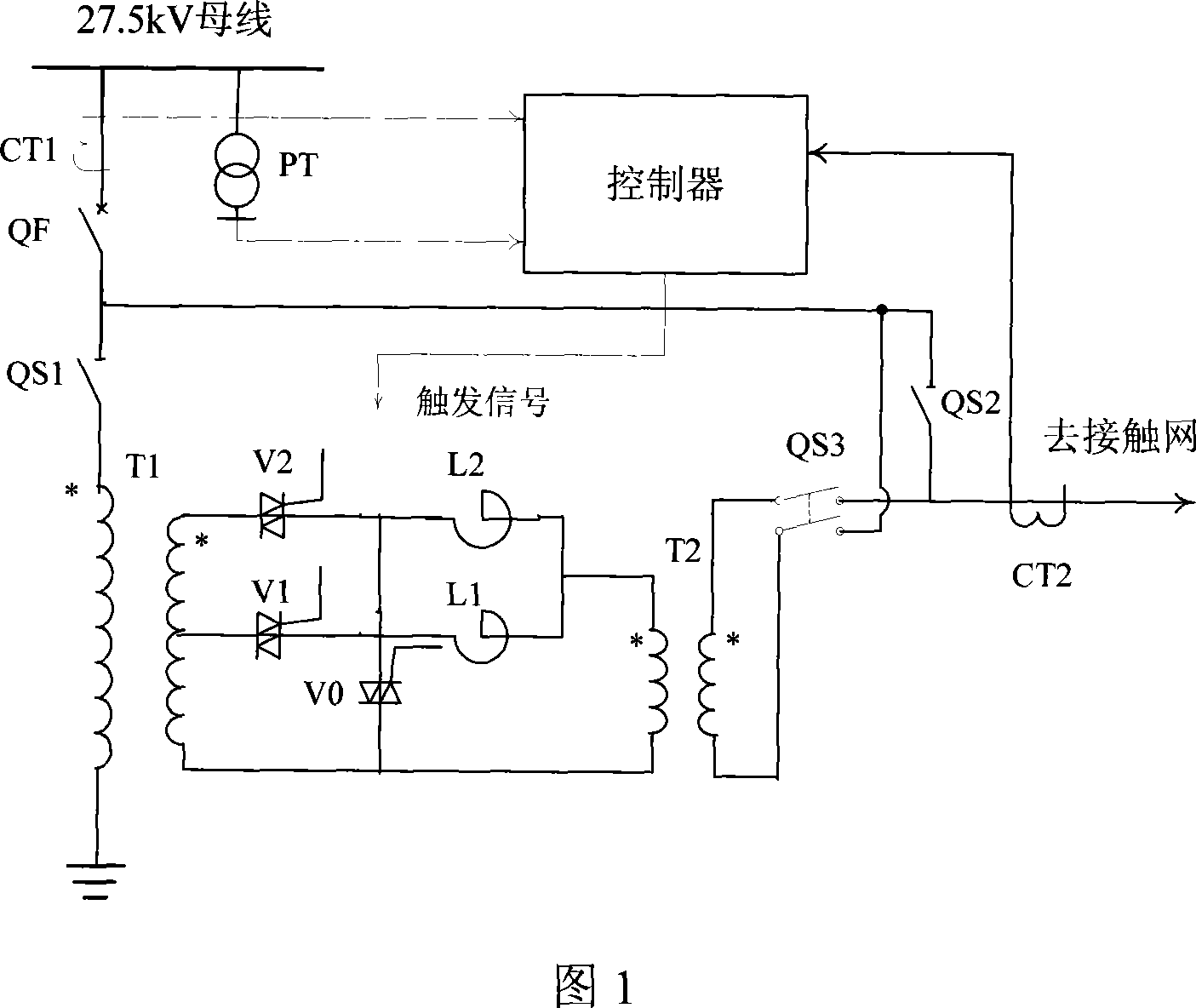
[0009] Figure 1 is an embodiment of a thyristor controlled series transformer type automatic voltage regulator for a traction network. In this embodiment, T1 is a step-down transformer, and there are 2 (or more, 2 in this embodiment) taps on the secondary side, which are connected to the 2 bidirectional thyristors V1 and V2 respectively, and the reactors L1 and L2. Branch circuits are connected, V0, V1, V2 are bidirectional thyristors, L1, L2 are reactors, T2 is series transformer, QS1, QS2 are isolation switches, QS3 is bipolar isolation switch, QF is circuit breaker, CT1, CT2 are current mutual inductances PT is a voltage transformer. When installed in a traction substation, the circuit breaker QF and current transformer CT1 can borrow the original equipment of the feeder, and the voltage transformer PT can borrow the original equipment of the traction bus. When installed in the middle of the power supply arm, the 27.5kV traction bus in Figure 1 is replaced with a power-side con...


PUM


Abstract

A thyristor control series transformer type traction electric network automatic voltage regulator which can be arranged inside a traction substation or on a middle part of a feeding section of a traction electric network consists of a step down transformer, a series transformer, a reactor, a bi-directional thyristor, a controller, a voltage transformer, a current transformer, a breaker and a isolating switch, etc.; the utility model is characterized in that: the step down transformer has a first side connected with a traction bus line and a second side provided with a plurality of tap joints respectively connected with a first side winding of the series transformer by the bi-directional thyristor and the reactor, a second side winding of the series transformer is connected in series with the traction electric network, the controller collects voltage and current signals of the traction electric network by the voltage transformer and the current transformer and controls switch-on and switch-off of the bi-directional thyristor by an inner voltage control logic, which results in automatically on-load adjusting the traction electric network voltage; the second side of the series transformer is provided with a bypass isolating switch; a side of the traction bus line and the traction electric network are respectively provided with current transformers in order to realize current differential protection.

Description

Technical field [0001] The invention belongs to the technical field of electrified railways, and specifically relates to a thyristor controlled series transformer type automatic voltage regulating device for an electrified railway traction network. Background technique [0002] Due to the rapid growth of transportation volume, many existing electrified railways in my country have the problem of low traction network voltage. Under heavy load, the voltage of the train at the end of the power supply arm is even lower than 19kV, while the rated voltage of electric locomotives and EMUs is 25kV , The voltage drop will affect the power of the train. Generally, trains below 19kV cannot operate normally, and even cause parking accidents. At present, shunt capacitor compensation devices are generally installed in traction substations, and some traction substations have also added auto-voltage regulating transformers to improve voltage. The main purpose of the shunt capacitor compensation d...

Claims


Application Information

Patent Timeline
Patent Type & Authority Applications(China)
IPC IPC(8): B60M3/00H02M5/12H02H7/22
Inventor 吴命利郑琼林游小杰杨少兵
Owner BEIJING JIAOTONG UNIV
Why Eureka
Try Eureka