

Blasting cap harvesters and collecting method
A collection machine and detonator technology, which is applied to weapon accessories, fuzes, offensive equipment, etc., can solve the problems of restricting the realization of automatic production lines, detonator explosion, low efficiency, etc., to avoid personal injury, ensure safe production, and improve work efficiency.
- Summary
- Abstract
- Description
- Claims
- Application Information
AI Technical Summary
Problems solved by technology
Method used
Image

Examples
Embodiment 1
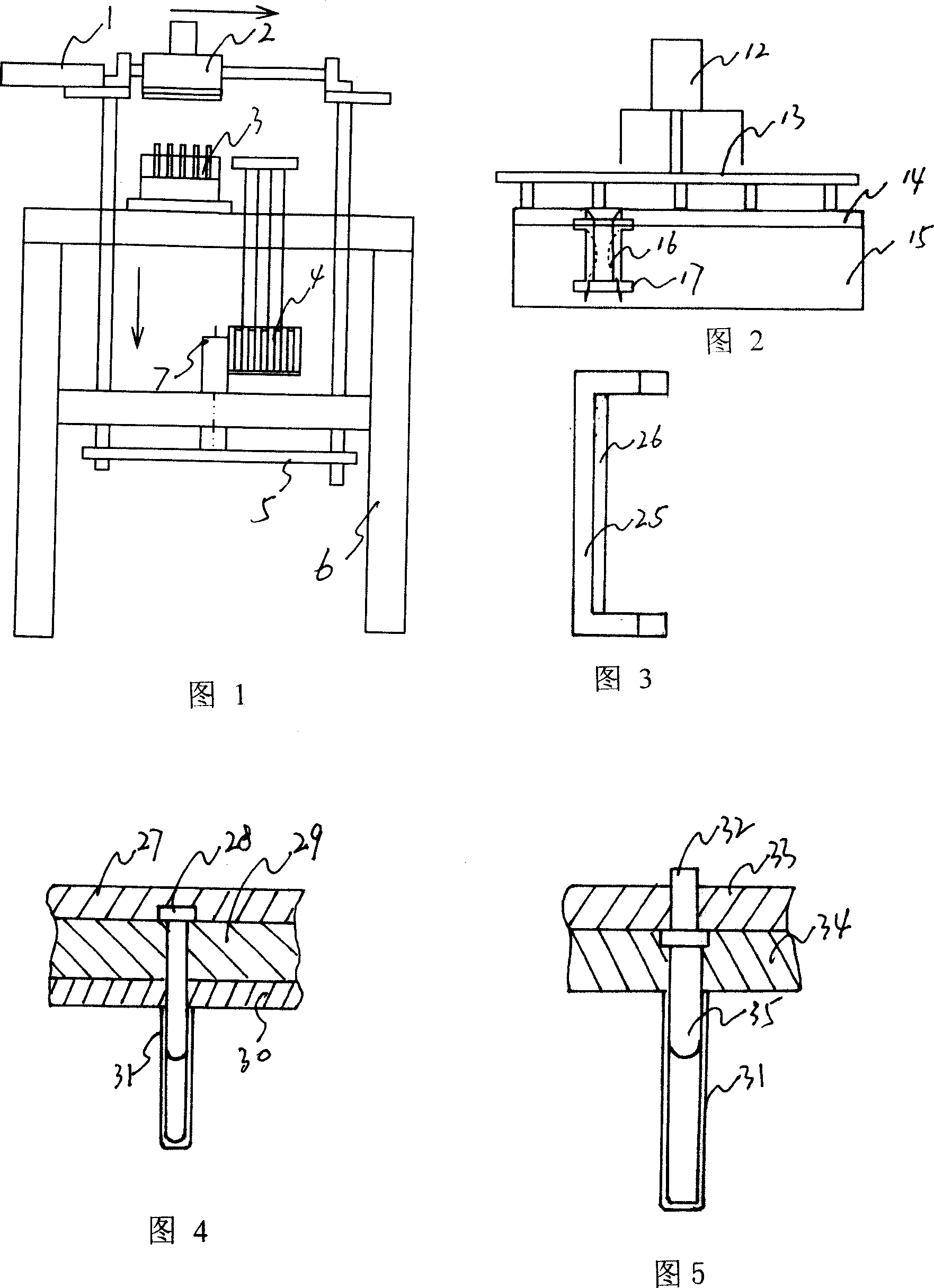
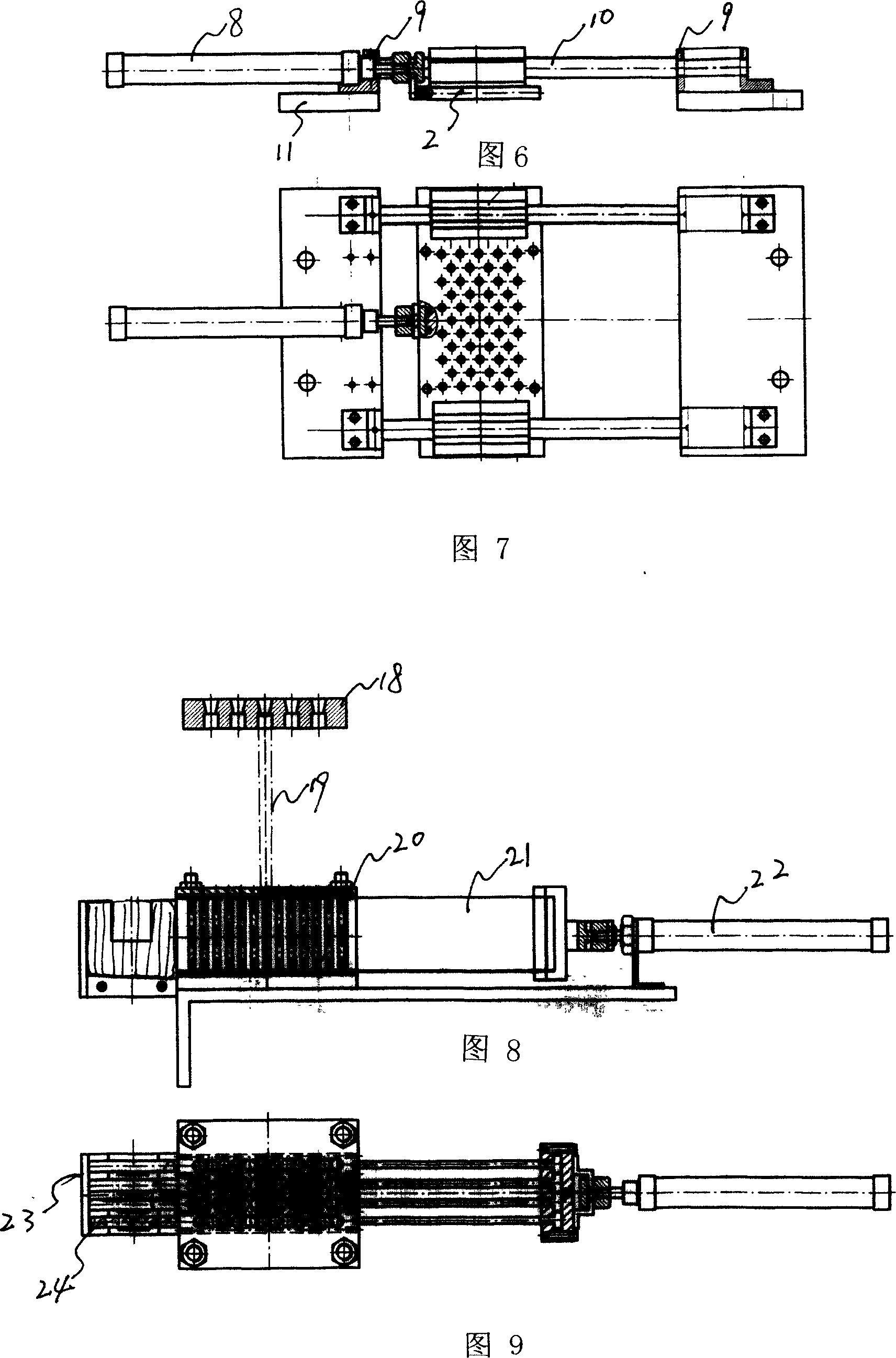
[0018] Embodiment 1: with reference to accompanying drawing 1~3 and 6~9. The fire detonator collector, the lifting mechanism 5 is composed of a lifting frame and a cylinder 7, the piston rod in the cylinder 7 drives the lifting frame 5 to move up and down and is processed by the prior art, the lifting mechanism 5 runs through the work surface of the frame 6, and the frame Make with reference to accompanying drawing 1 by prior art processing. The translation mechanism 1 is located at the upper end of the lifting mechanism. The translation mechanism 1 is composed of a support block 9, a guide rod 10 and a cylinder 8. The two ends of the guide rod 10 are respectively connected with the support block. The piston rod in the support block is connected with the grabbing mechanism of the fire detonator through the through hole in the support block. The fire detonator grasping mechanism 2 adopts a linear bearing sleeve on the guide rod of the translation mechanism 1. The fire detonato...
Embodiment 2
[0019] Embodiment 2: On the basis of Embodiment 1, refer to accompanying drawing 4. The fire detonator grasping mechanism 2 comprises upper cover plate 27, many magnetic steel bolts 28, middle plate 29 and shell stripping plate 30. The steel bolts 28 are embedded between the formwork formed by the superposition of the upper cover plate 27, the middle plate 29 and the shell stripping plate 30. When grabbing the shell of the fire detonator, a plurality of magnetic steel bolts 28 on the formwork will be placed under the action of the external force (cylinder) mechanism. Under driving, insert respectively in the respective fire detonator casing 31, and fire detonator casing 31 is sucked by magnetic steel bolt 28, and after fire detonator grasping mechanism 2 moves to designated position under the effect of external force (cylinder) driving mechanism, by middle The integral movable plate that plate 29 and upper cover plate 27 constitute moves backward under the drive of external fo...
Embodiment 3
[0020] Embodiment 3: On the basis of Embodiment 1 and 2, with reference to accompanying drawing 4. The fire detonator grasping mechanism 2 comprises upper plate cover 27, magnetic steel bolt 28 and shell stripping plate 30 and shell stripping plate 30 is a fixed plate, and upper cover plate 27 is a movable plate, and a plurality of magnetic steel bolts 28 are embedded in the Between the templates where the plate 27 and the stripping plate 30 are superimposed, when grabbing the fire detonator shell, the multiple magnetic steel bolts 28 on the template are inserted into the respective fire detonator shells 31 under the drive of the external force (cylinder) mechanism , the fire detonator shell 31 is sucked by the magnetic steel bolt 28, after the fire detonator grasping mechanism 2 moves to the designated position under the action of the external force (cylinder) driving mechanism, the upper cover plate 27 moves backward under the drive of the external force (cylinder) mechanism ...
PUM
 Abstract
Description
Claims
Application Information