Electromagnet horizontal mobile section steel automatic packing machine

An automatic packaging machine and horizontal movement technology, applied in the direction of packaging, transportation and packaging, conveyor objects, etc., can solve the problems of increasing electromagnet spare parts storage, low manpower lifting efficiency, complex electromagnet structure, etc., to increase spare parts storage , Saving spare parts storage expenses, the effect of fast working frequency

Inactive Publication Date: 2008-02-13
李力行
View PDF0 Cites 10 Cited by
  • Summary
  • Abstract
  • Description
  • Claims
  • Application Information

AI Technical Summary

Problems solved by technology

[0003] 1) Manpower palletizing; due to the low efficiency of manpower lifting, it is only suitable for small and medium-sized section steel production or small batch production of section steel
[0004] 2) Imported electromagnet flip-type automatic section steel packaging machine, this equipment adopts a large rocker arm overall structure, advanced technology, can meet modern production, but the manufacturing technology is complicated, the equipment is expensive, and the electromagnet in the equipment needs to drive the rolling piece to swing, Flipping, in order to ensure that the rolled piece does not fall off and is not in place during the movement, the electromagnet is required to be made according to the cross-sectional shape of the section steel, so the electromagnet structure is complicated, the manufacturing cost is high, and the electromagnet needs to be replaced frequently according to the product specification, which greatly increases the electromagnet. Spare parts reserve, currently this kind of equipment is only assembled in a few large enterprises in China
[0005] 3) Half swing arm and half gantry crane type packaging machine, the electromagnet of this equipment does not turn over, the equipment structure is complicated, the weight is heavy, and the manufacturing cost is high. Each set costs more than 5 million yuan, which cannot be generally applied to general steel mills

Method used


Image

  • Electromagnet horizontal mobile section steel automatic packing machine
  • Electromagnet horizontal mobile section steel automatic packing machine
  • Electromagnet horizontal mobile section steel automatic packing machine

Examples


Embodiment Construction

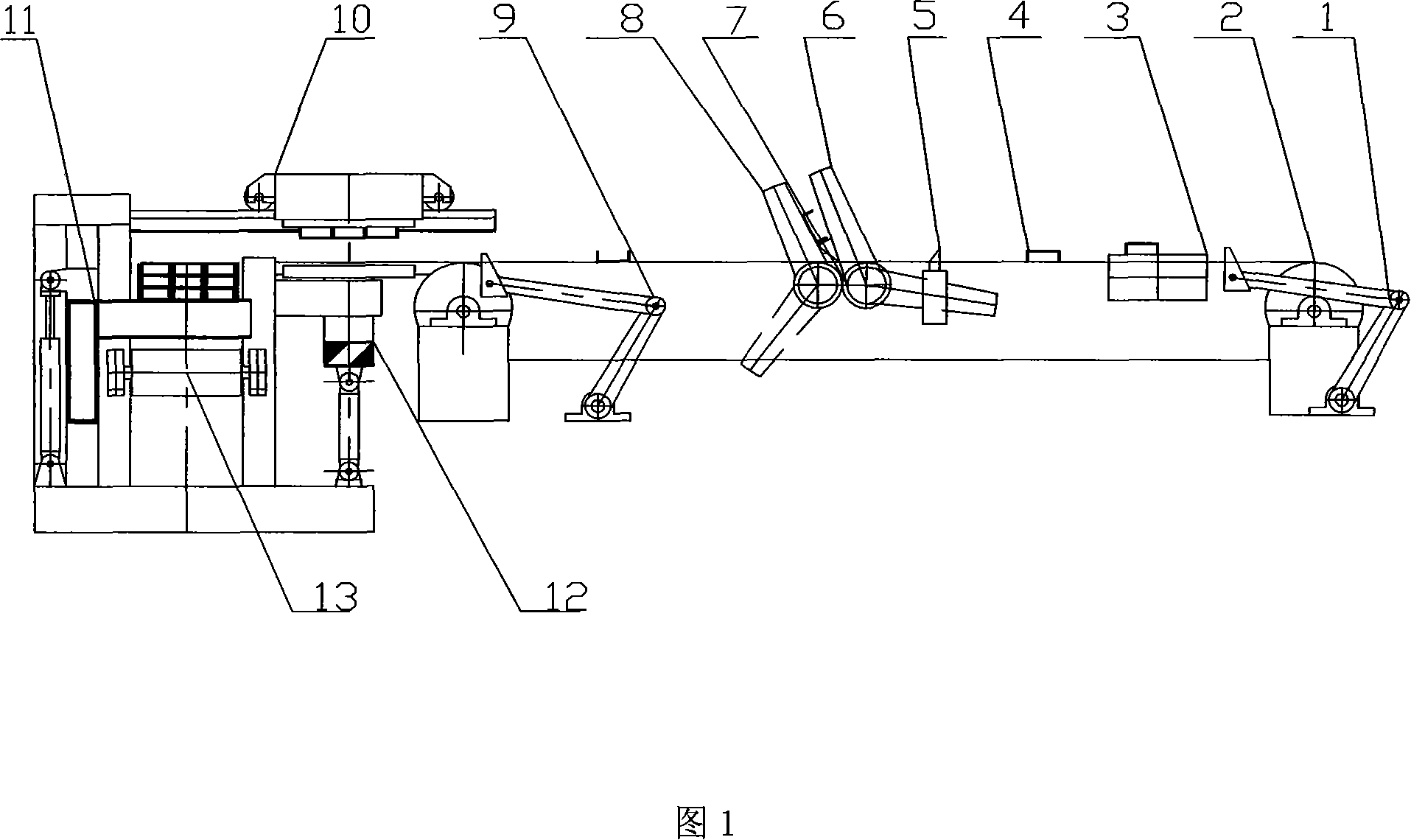
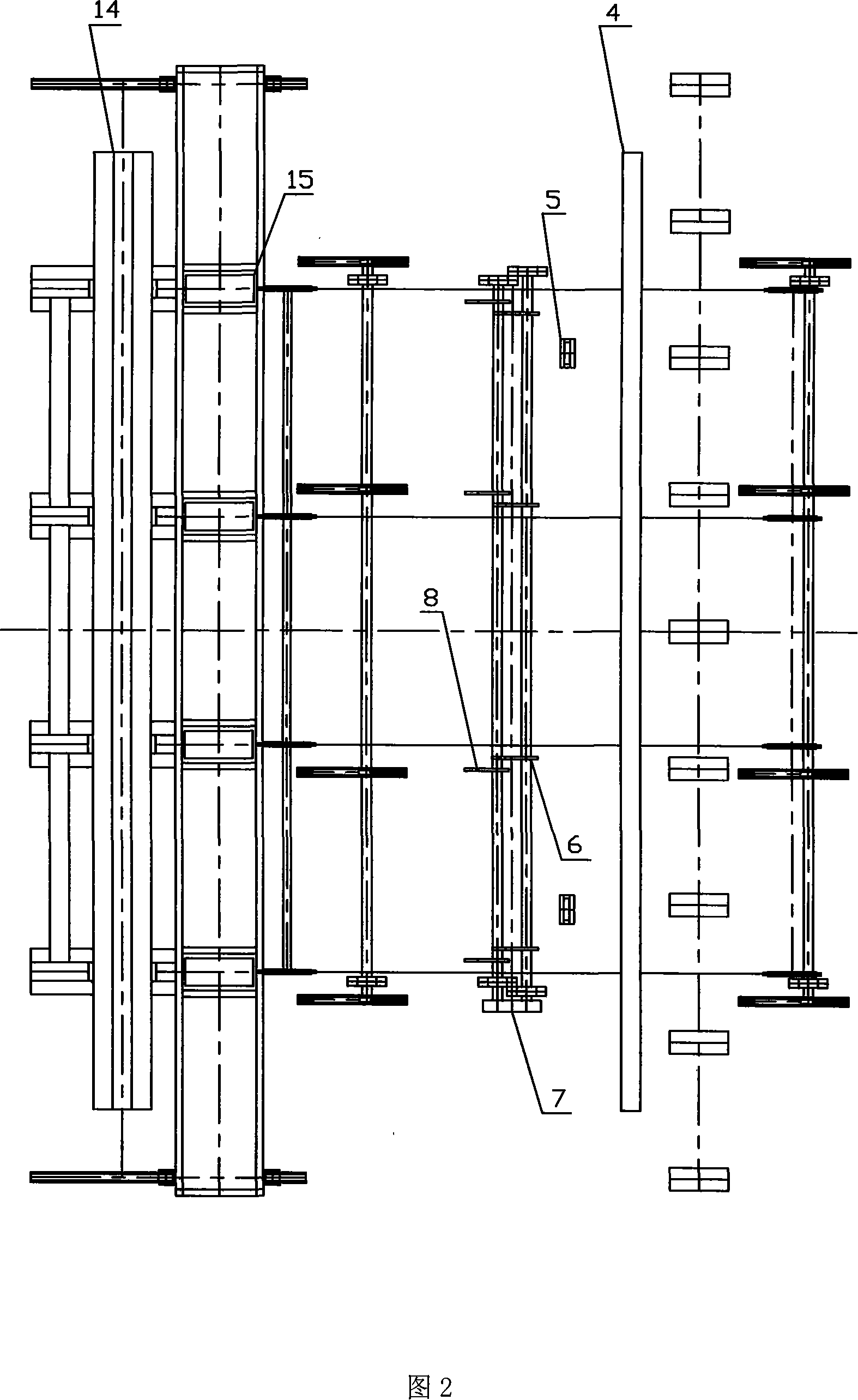
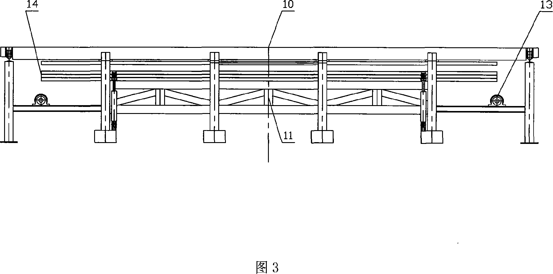
[0021] An electromagnet horizontally moving type steel automatic packaging machine, the device is composed of several separate parts: a single-row steel lifting mechanism 12, an electromagnet trolley 10, a piled steel lifting mechanism 11, a steel tight device 9, and a steel turning mechanism. The single-row shaped steel lifting mechanism 12 is located at the end of the chain conveying mechanism 2, and its upper part is provided with a track on which a horizontally moving electromagnet trolley 10 is arranged; the stacked shaped steel lifting mechanism 11 is arranged on the top of the stacked shaped steel output roller table 13 . The end of the chain conveying mechanism 2 is provided with a profiled steel abutment device 9; the chain conveying mechanism 2 is provided with a profiled steel overturning mechanism, and the profiled steel overturning mechanism is sent by the overturning mechanism to the steel arm 6, the overturning mechanism gear shaft 7, and the overturning mechanis...


PUM


Abstract

The present invention relates to an automatic packer of electromagnet horizontal shift type for a profiled bar. The device consists of a profiled bar elevating mechanism of single row, an electromagnet dolly and a monomer structure of a mounded profiled bar elevating mechanism. The profiled bar elevating mechanism of single row is located at the end of a chain feeding mechanism, on which a track is arranged. The electromagnet dolly is arranged on the track, moving horizontally. The mounded profiled bar elevating mechanism is arranged at the upside of an output roll table of the mounded profiled bar. The technology of the present invention adopts the simple and cabinet structural form of equipment with the advantages of single movement, simple structure, and low technological requirement on the manufacture technics and on the automatization. The manufacture cost of the whole equipment is between 600thousand and 700 thousand Yuan per set, one in few tens of the prior equipment cost. Because of the less investment cost of the packer of the present invention, the present invention is applicable to most of profiled bar manufacturer, which is convenient to be extended.

Description

technical field [0001] The invention relates to a packaging device for finished section steel, in particular to an electromagnet horizontally moving automatic packaging machine for section steel. Background technique [0002] At present, there are mainly three types of steel packaging processes after steel rolling production: [0003] 1) Manpower palletizing; due to the low efficiency of manpower lifting, it is only suitable for the production of small and medium-sized section steel or small batches of section steel. [0004] 2) Imported electromagnet flip-type automatic section steel packaging machine, this equipment adopts a large rocker arm overall structure, advanced technology, can meet modern production, but the manufacturing technology is complicated, the equipment is expensive, and the electromagnet in the equipment needs to drive the rolling piece to swing, Flipping, in order to ensure that the rolled piece does not fall off and is not in place during the movement,...

Claims


Application Information

Patent Timeline
Patent Type & Authority Applications(China)
IPC IPC(8): B65B27/10B65B35/30B65B35/50B65B35/56B65G57/18B65G47/24
Inventor 李力行
Owner 李力行
Why Eureka
Try Eureka