Air conditioner

An air conditioner and air technology, applied in the field of air conditioners, can solve the problems of high equipment cost and high operating cost

Active Publication Date: 2008-02-20
KIMURA KOHKI CO LTD
View PDF1 Cites 7 Cited by
  • Summary
  • Abstract
  • Description
  • Claims
  • Application Information

AI Technical Summary

Problems solved by technology

[0007] However, in the air-conditioning apparatus of Patent Document 1, the above-mentioned problems of high equipment cost and high running cost cannot be solved.

Method used


Image

  • Air conditioner
  • Air conditioner
  • Air conditioner

Examples


Embodiment approach 1

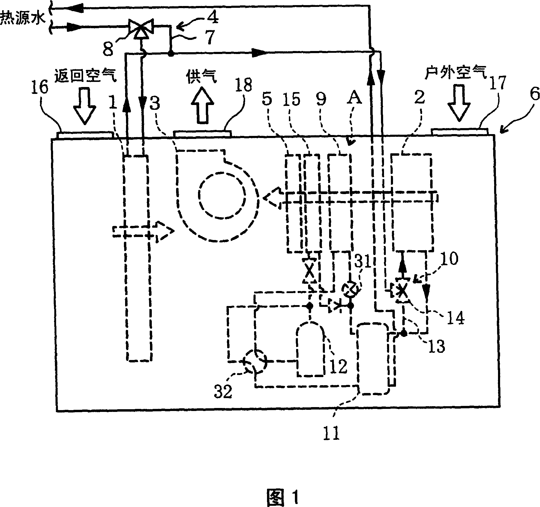
[0081] Hereinafter, the present invention will be described in detail based on the drawings showing its embodiments. FIG. 1 is a schematic diagram showing the configuration of main parts of an air conditioner according to Embodiment 1 of the present invention.

[0082] The air conditioner according to Embodiment 1 is equipped with an outdoor air inlet 17 for taking in external outdoor air, a return air inlet 16 for taking in indoor return air, and a mixing air inlet 16 provided on one surface. The outside air and return air are supplied to the housing 6 of the air supply 18 for indoor air supply. The outdoor air inlet 17 communicates with the outside through ducts and the like, and the return air inlet 16 and the air supply port 18 communicate with the indoors through ducts and the like, respectively.

[0083] The outdoor air entering the housing 6 through the outdoor air inlet 17 and the return air entering the housing 6 through the return air inlet 16 are mixed by the sucti...

Embodiment approach 2

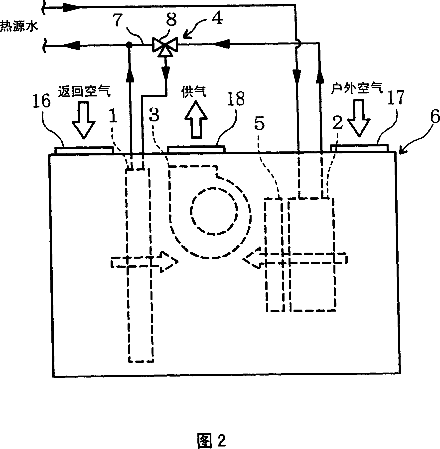
[0107] Fig. 2 is a schematic diagram showing a configuration of main parts of an air conditioner according to Embodiment 2 of the present invention. The air conditioner according to the second embodiment has the same main part configuration as the air conditioner according to the first embodiment, but the water heat source heat pump is omitted.

[0108] The air conditioner according to Embodiment 2 includes, in the casing 6 , a return air treatment coil 1 for exchanging heat with return air, a first outdoor air treatment coil 2 for exchanging heat with outdoor air, and a first outdoor air treatment coil 2 for exchanging heat with the return air treatment coil 1 . The return air and the outdoor air heat-exchanged by the first outdoor air treatment coil 2 are mixed to supply air to the room by the suction blower 3 , and the humidifier 5 is used to humidify the outdoor air heat-exchanged by the first outdoor air treatment coil 2 . In addition, the return air treatment coil 1 is d...

Embodiment approach 3

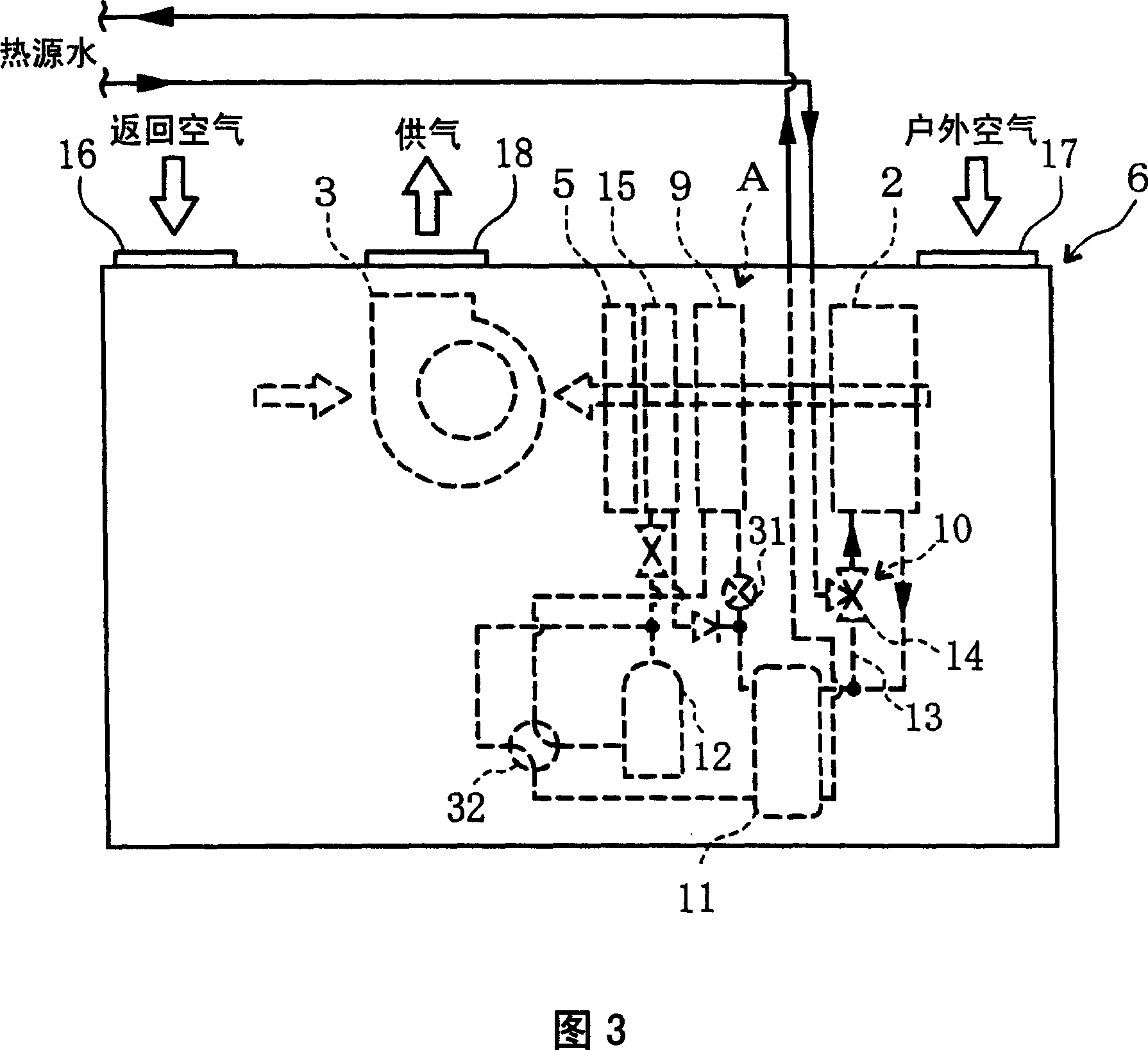
[0122] Fig. 3 is a schematic diagram showing a configuration of main parts of an air conditioner according to Embodiment 3 of the present invention. The air conditioner according to the third embodiment has the same main part configuration as the air conditioner according to the first embodiment, but the return air processing coil is omitted.

[0123] The air conditioner according to Embodiment 3 is provided in the casing 6 with: a first outdoor air treatment coil 2 for exchanging heat with outdoor air and a second outdoor air treatment coil 9 for a water heat source heat pump A; a humidifier 5 for humidifying the outdoor air; The suction type blower 3 which mixes the outdoor air processed by the 1st outdoor air processing coil 2, the 2nd outdoor air processing coil 9, and the humidifier 5, and return air, and supplies air. The return air inlet 16 is arranged to face the second outdoor air treatment coil 9 and the humidifier 5, and the blower 3 is provided therebetween. On on...


PUM


Abstract

The invention provides an air conditioner, such as on the refrigerating operation on summer, after respectively cooling return air and outside air to make the temperature of return air higer than the ouside air, the return air and outside air is mixed to apply air to indoor to omit reheating, and the operation cost can be reduced, in addition, because it is unnecessary flow through reheated warm water, a two tubular type of heat source water loop for only flowing through cool water is formed, therefore the device cost is reduced. The said air conditioner is provided with return air treatment coil (1) for exchanging the return air, a first outside air treatment coil (2) for heat exchanging the outside air and a second outside air treatment coil (9), a blower for applying air to indoor after the return air and outside air respectively sujected to heat exchange.

Description

technical field [0001] The present invention relates to an air conditioner that mixes return air and outdoor air to supply air to a room. Background technique [0002] A conventional air conditioner (or air conditioner) of the so-called outdoor air hybrid type that mixes outdoor air and return air mixes outdoor air from the outside with return air from the room, and then mixes the mixed air (hereinafter referred to as air conditioning). Mixed gas) cooling, dehumidification, heating, etc. For example, in cooling operation in summer, air-fuel mixture is temporarily dehumidified by supercooling, reheated (reheated) to control humidity, and air is supplied into the room (for example, refer to Patent Document 1). [0003] However, in this type of air conditioner, since the air mixture is cooled and reheated, it is not only necessary to cool and reheat both the outdoor air and the return air constituting the air mixture, but also to flow through the air as air for cooling and reh...

Claims


Application Information

Patent Timeline
Patent Type & Authority Applications(China)
IPC IPC(8): F24F3/153F24F3/12
CPCF24F7/08F24F12/003F24F13/30F25B30/04
Inventor 木村惠一长岛信雄森田满津雄笠原和行
Owner KIMURA KOHKI CO LTD
Why Eureka
Try Eureka