
A pulse constant energy charging method and its charging device for lead acid battery

A lead-acid battery and charging device technology, applied in battery circuit devices, secondary battery charging/discharging, circuit devices, etc., can solve the problem of not being able to achieve the best charging mode of lead-acid batteries, limiting the service life of lead-acid batteries, and adversely affecting batteries. Service life and other issues, to avoid soft failure, low cost and high reliability

Inactive Publication Date: 2008-02-20
郑德明 +1
View PDF1 Cites 9 Cited by
  • Summary
  • Abstract
  • Description
  • Claims
  • Application Information

AI Technical Summary

Problems solved by technology

The pulse charging control method has already been adopted in the existing storage battery charging device, such as the utility model patent 00201335.5 "New Fast Pulse Charger", which introduces a charger using the pulse charging current mode, but it is not conducive to the service life of the storage battery and also Some constant voltage charging is easy to over-current when the battery potential is low; and constant current charging is easy to overload and generate heat when the battery potential is high. Both of them are equipped with chemical reaction process during electric energy conversion, which cannot achieve the best performance for lead-acid batteries. The requirements of the best charging mode limit the service life of lead-acid batteries

Method used


Image

  • A pulse constant energy charging method and its charging device for lead acid battery
  • A pulse constant energy charging method and its charging device for lead acid battery

Examples


Embodiment Construction

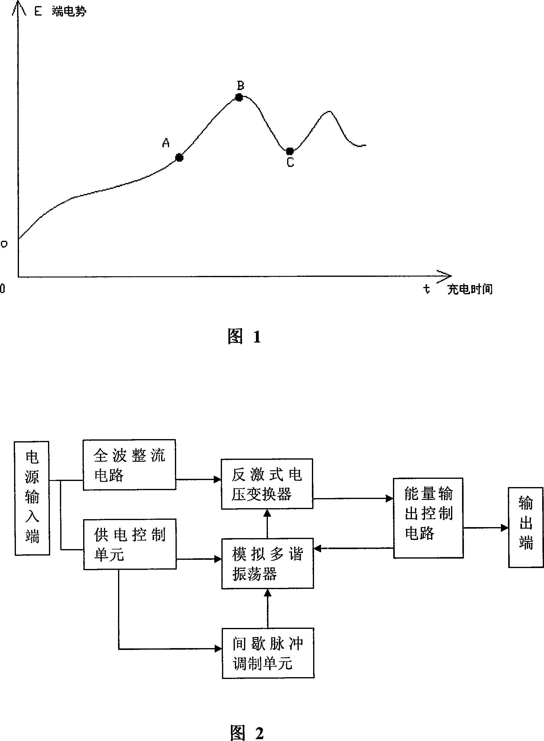
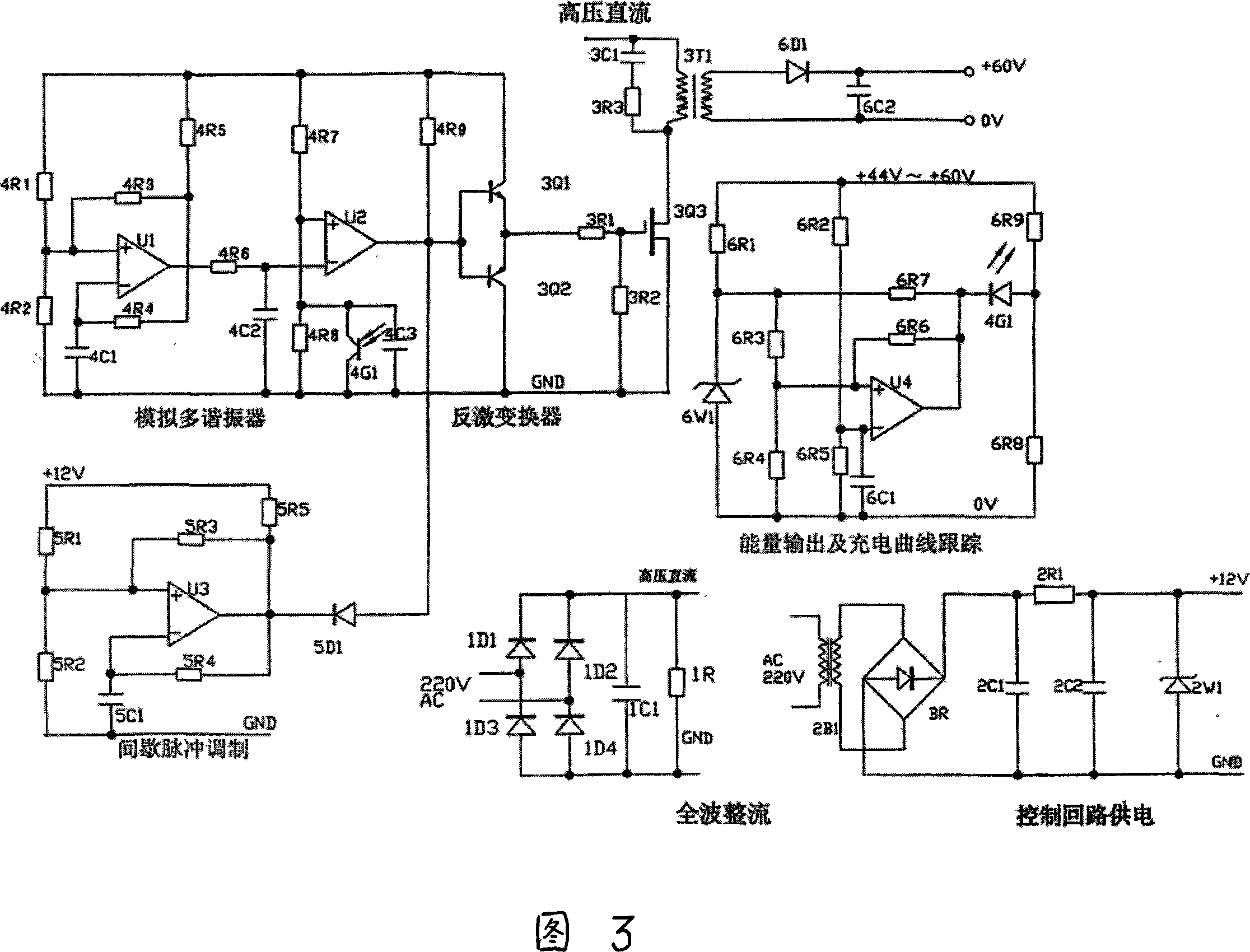
[0021]The AC 220V voltage is rectified by the rectifier bridge stack in the full-wave rectifier circuit and converted into a DC 310V working power supply through capacitor filtering, which supplies power to the flyback voltage converter. The AC 220V voltage is also passed through the transformer in the power supply control unit After 2B1 is stepped down, it is rectified by the rectifier bridge BR, filtered by capacitors 2C1 and 2R1, and stabilized by the regulator tube 2W1 to provide +12 volts to the entire control circuit; the voltage comparator U1 in the multivibrator uses LM339, multivibrator The oscillation frequency of the oscillator is determined by 4R4 and 4C1, about 50KHZ, and 4R5 is a pull-up resistor. 4R6 and 4C2 transform the output waveform of U1 so that the negative phase input of U2 is a triangle wave. Under the action of 4R7 and 4R8, the pulse width output by U2 is controlled by the optocoupler 4G1. When 4G1 is turned on, the pulse width output by U2 will gradua...


PUM


Abstract

The utility model provides a constant energy charging method for the lead-acid battery and a related charger, which converts the AC voltage into the DC voltage, and then into a lower voltage which is adapted with the charging voltage of the battery, the battery is charged in a manner of controlled intermittent impulse and constant energy. The control process of the constant energy is that: the charging current and the voltage of the battery is detected and analyzed, and then the charging potential is changed automatically according to the normal potential curve for the electrochemical reaction of the charged battery. The utility model has the advantages that implementing the automatically self adaptive control of the charging process with a simple circuit and low cost, reducing the mechanical stress from the twinkling fluctuation on the charging voltage, preventing the plates of the battery from being damaged, and prolonging the service life of the lead-acid battery significantly.

Description

technical field [0001] The invention relates to a charging method for a lead-acid storage battery and a charging device thereof, in particular to a pulse constant energy charging method and a pulse constant energy charging device thereof. Background technique [0002] Due to the rise of electric vehicles in recent years, lead-acid batteries are widely used in industries such as mopeds and telecommunications. In the past, the acid battery was mainly used as a backup for the main power supply, and the working mode of strong discharge and strong charging like a moped is not good for the battery, so many charging modes that have existed in the past are no longer suitable for the current strong charging process. too suitable. The working principle of the lead-acid battery is to convert electrical energy into chemical energy for energy storage, and the discharge is converted from chemical energy into electrical energy to provide electrical energy to the load. The pulse charging ...

Claims


Application Information

Patent Timeline
IPC IPC(8): H02J7/00H01M10/44
CPCY02E60/12Y02E60/10
Inventor 李顺生
Owner 郑德明
Learn More