
Electric scooter radio remote controller and controller thereof

An electric scooter and controller technology, applied in electrical program control, electric vehicle charging technology, comprehensive factory control, etc., can solve the problems of wires involved in the flywheel, power consumption, safe distance pollution, large starting current, etc. Safety and reliability, flexible and convenient control, and the effect of transmitting a large amount of information

Inactive Publication Date: 2008-02-27
JIANGNAN UNIV
View PDF0 Cites 12 Cited by
  • Summary
  • Abstract
  • Description
  • Claims
  • Application Information

AI Technical Summary

Problems solved by technology

[0002] At present, electric scooters are mainly controlled by wires, so the flexibility of electric scooters is greatly limited, and it is difficult for sports people to slide out various actions in their own way as they like. This will lose the original fun of scooter sports
The wired control method makes it inconvenient to carry, and the wires are often involved in the flywheel, causing major life safety accidents
Now there are remote control electric scooters on the market, but there are still many defects in terms of power consumption, safety, distance, pollution, etc.
There are still many defects in the electric scooter controller in terms of motor starting current, motor noise, power consumption of the control circuit, etc.
For example: the motor is required to start very fast, and the starting speed from zero to the maximum value must be limited within a certain period of time, but the starting current required to start the motor in such a short time is very large, and the battery is seriously damaged.

Method used


Image

  • Electric scooter radio remote controller and controller thereof
  • Electric scooter radio remote controller and controller thereof
  • Electric scooter radio remote controller and controller thereof

Examples


Embodiment Construction

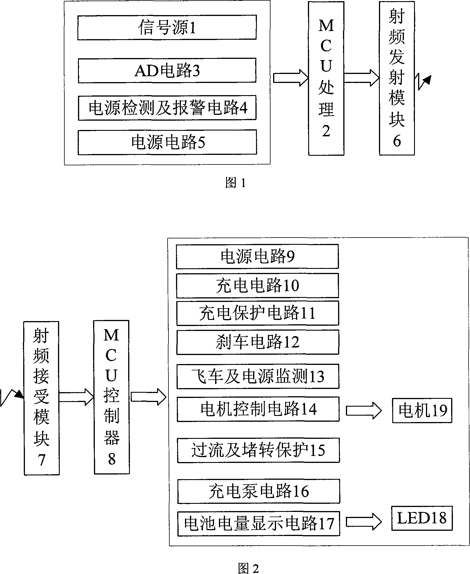
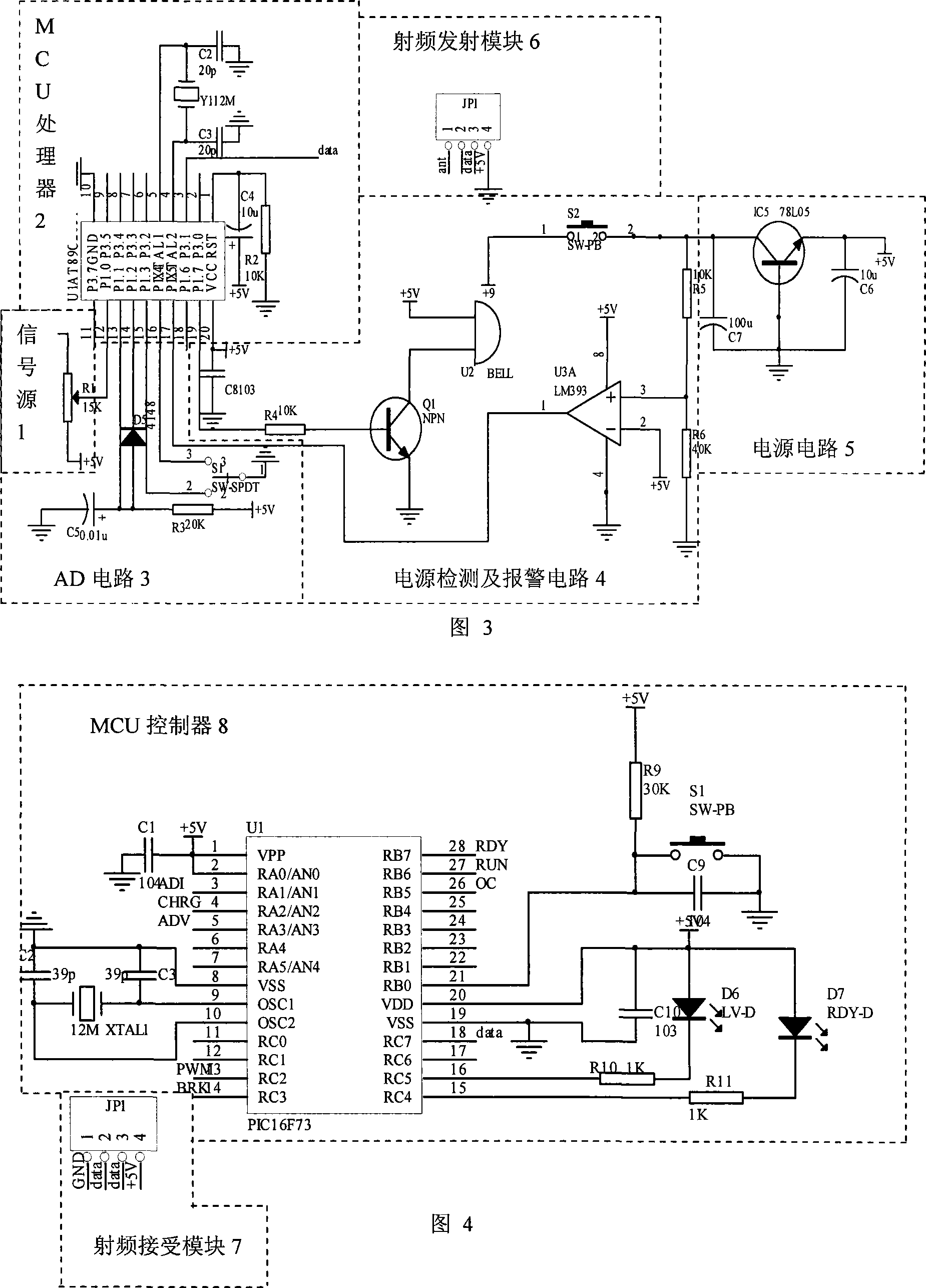
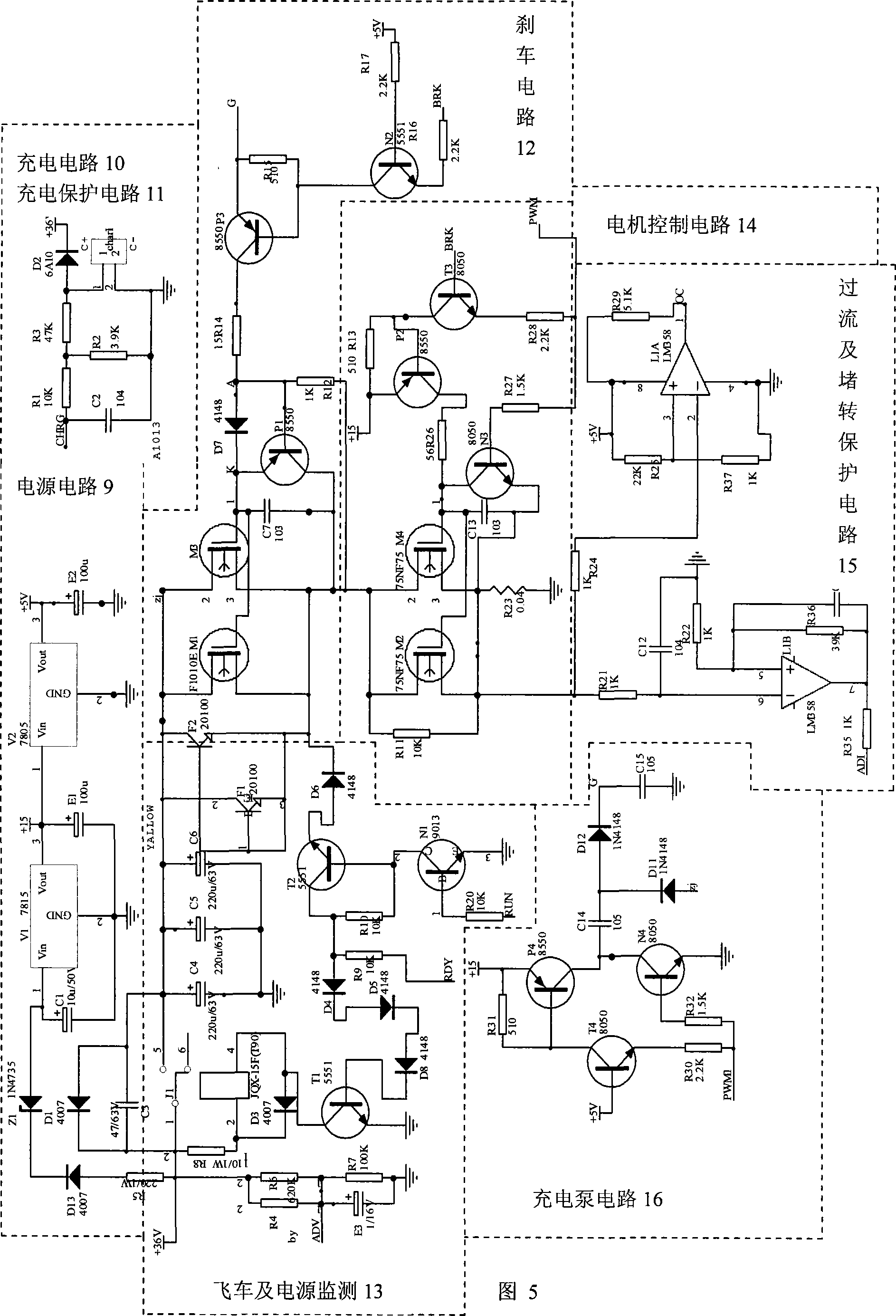
[0023] As shown in the figure: the present invention includes a remote control transmission part and a remote control reception control part, wherein the remote control transmission part includes a signal source 1, an MCU processor 2, and a radio frequency transmission module 6; wherein the output terminal of the signal source 1 is connected to the MCU processor 2, The signal of the signal source 1 is processed by the MCU processor 2, and becomes a transmissible binary signal with control information and password information; the binary signal directly drives the RF transmitter module 6 through the serial port output of the MCU processor 2; the control information and password information Emitted by the radio frequency transmitting module 6;

[0024] The remote control receiving control part includes a radio frequency receiver 7, an MCU controller 8, a motor speed control circuit 13, a flying car protection and power supply monitoring circuit 12, a battery undervoltage protecti...


PUM


Abstract

This invention is a sort of control device which controls the operation of the dynamo-electric sliding vane bus. It is this device which controls the operation of the dynamo-electric sliding vane bus by the remote control technique. According to the techno-method offered by this invention this invention consists two parts, this first part is the remote control emission, the request of the transmitted power of this part is high, the transmitted power of processor reaches 10 milliwatt, the transmission distance is in the range of 10 meter. The second part if the control of the remote control receiver, this part realizes the control to the operation of the electromotor of the sliding vane bus. This remote controller uses the digit control signal of the radio-frequency transmission to control the sliding vane bus; it realizes the infinite speed regulating control to the electromotor of the sliding vane bus. The controller is the actuating mechanism of the operating instruction of the controller, it controls the operating mode of the electromotor, and it carries out the infinite speed variation of the electromotor and the braking. It progresses the monitor to the estate of the electromotor, it the fly-bus happens or the people deviates the sliding vane bus, stop the operation of the sliding vane bus, and stop the answer to the control signal of the remote controller.

Description

technical field [0001] The invention is a device for controlling the operation of the electric scooter, especially a device for controlling the operation of the scooter by remote control technology. Background technique [0002] At present, electric scooters are mainly controlled in a wired way, so the flexibility of electric scooters is greatly limited, and it is difficult for sports people to slide out various actions in their own way as they like. This has also lost the original fun of scooter motion. The wired control method makes it inconvenient to carry, and the wires are often involved in the flywheel, causing major life safety accidents. There are also remote control electric scooters on the market now, but there are still many defects in terms of power consumption, safety, distance, pollution, etc. There are still many defects in the electric scooter controller in terms of motor starting current, motor noise, and power consumption of the control circuit. For exam...

Claims


Application Information

Patent Timeline
Patent Type & Authority Applications(China)
IPC IPC(8): G05B19/418G08C17/00G08C17/02
CPCY04S30/12Y02T90/168Y02T90/167
Inventor 周达左杨慧中潘国锋
Owner JIANGNAN UNIV
Learn More