

Method for activating membrane electrode of fuel cell
A fuel cell membrane and activation method technology, which is applied to fuel cell parts, battery electrodes, battery circuit devices, etc., can solve the problems of long activation time, achieve high output power, uniform area activation, and shorten activation time
- Summary
- Abstract
- Description
- Claims
- Application Information
AI Technical Summary
Problems solved by technology
Method used
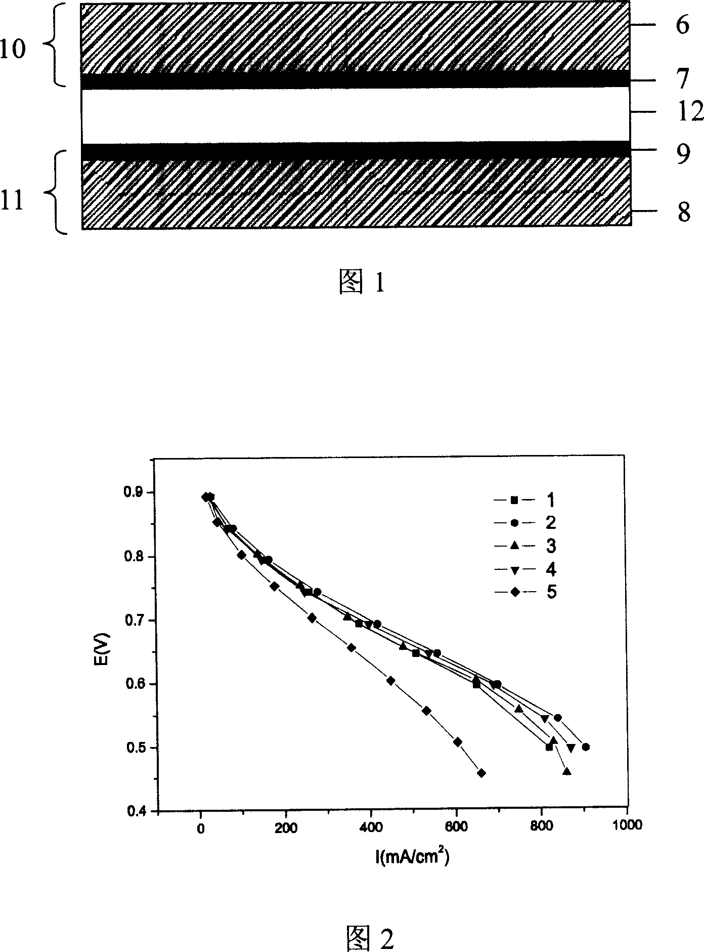
Image

Examples
Embodiment 1
[0027] This embodiment illustrates the activation method of the fuel cell membrane electrode provided by the present invention
[0028] 1. Preparation of Membrane Electrode
[0029] (1) 0.2 parts by weight of carbon black (Vulcan XC72R, Cabot company) and 0.1 parts by weight of PTFE emulsion (FR303A, Shanghai Sanaifu New Material Co., Ltd.) with a solid content of 60% by weight, and 10 parts by weight of deionized water are mixed , ultrasonically dispersed for 30 minutes to obtain a carbon dispersion, and then the carbon dispersion was coated on carbon paper (TGP-H-90, Toray Company), and the weight gain of the carbon paper after drying at 100°C was 1 mg / cm 2 , and then placed in a high-temperature oven at 350 ° C for 20 minutes to obtain a gas diffusion layer;
[0030] (2) 0.2 parts by weight of Pt / C catalyst (Hispec8100, product of Johnson Matthey Company) with platinum loading of 47.7% by weight and 2 parts by weight of nafion dispersion (DE520, product of DUPONT Company) ...
Embodiment 2
[0037] This embodiment illustrates the activation method of the fuel cell membrane electrode provided by the present invention
[0038] Prepare and activate the membrane electrode according to the method of Example 1, the difference is that the temperature of the battery is controlled to be 65 ° C, the humidification temperature of the anode and cathode fuel is 60 ° C, and the relative humidity is 100%, and the positive electrode of a stabilized power supply and The negative electrode is connected to the anode and cathode of the fuel cell respectively, and the current of the regulated power supply is adjusted to stabilize the current density of the fuel cell at 0.05 ampere / cm 2 , discharge the fuel cell for 10 minutes, and then continue to adjust the current of the regulated power supply to stabilize the current density of the fuel cell at 0.08 ampere / cm 2 , discharge the fuel cell for 10 minutes, and continue to adjust to stabilize the discharge current density of the fuel ce...
Embodiment 3
[0040] This embodiment illustrates the activation method of the fuel cell membrane electrode provided by the present invention
[0041] Prepare and activate the membrane electrode according to the method of Example 1, except that the temperature of the battery is controlled at 55° C., the humidification temperature of the anode and cathode fuels is 50° C., and the relative humidity is 80%. Adjust the current of the external power supply to stabilize the current density of the fuel cell at 0.4 amps / cm 2 , discharge the fuel cell for 10 minutes, and then continue to adjust the current of the external power supply to make the current density of the fuel cell 0.72 amperes / cm 2 , discharge the fuel cell for 30 minutes, then disconnect the external power supply, stop the discharge of the fuel cell, let it stand for 2 minutes, and then adjust the current of the external power supply again to stabilize the current density of the fuel cell at 0.4 ampere / cm 2 , 1.0 A / cm 2 , discharge ...
PUM
 Abstract
Description
Claims
Application Information