Burr testing apparatus

A detection device and burr technology, applied in real-time pulse transmission devices, pulse processing, electrical components, etc., can solve the problems of complex circuit structure, undetectable, undetectable burrs, etc., and achieve the effect of easy implementation and simple circuit

Inactive Publication Date: 2008-03-12
UNIV OF ELECTRONIC SCI & TECH OF CHINA
View PDF0 Cites 24 Cited by
  • Summary
  • Abstract
  • Description
  • Claims
  • Application Information

AI Technical Summary

Problems solved by technology

[0012] Due to the time delay between D flip-flop D1 and D flip-flop D2 in Figure 1 and the feedback signal, some circuits must use separate devices, making the circuit structure complex, and as shown in Figure 3, the change of the output databack of D flip-flop D2 Ther

Method used


Image

  • Burr testing apparatus
  • Burr testing apparatus
  • Burr testing apparatus

Examples


Example Embodiment

[0026] The following describes preferred specific embodiments of the present invention in conjunction with the accompanying drawings. It is to be noted that similar parts are given similar reference numerals even though they appear in different drawings. Also, in the following description, when detailed descriptions of known functions and designs employed may obscure the subject matter of the present invention, such descriptions will be omitted here.

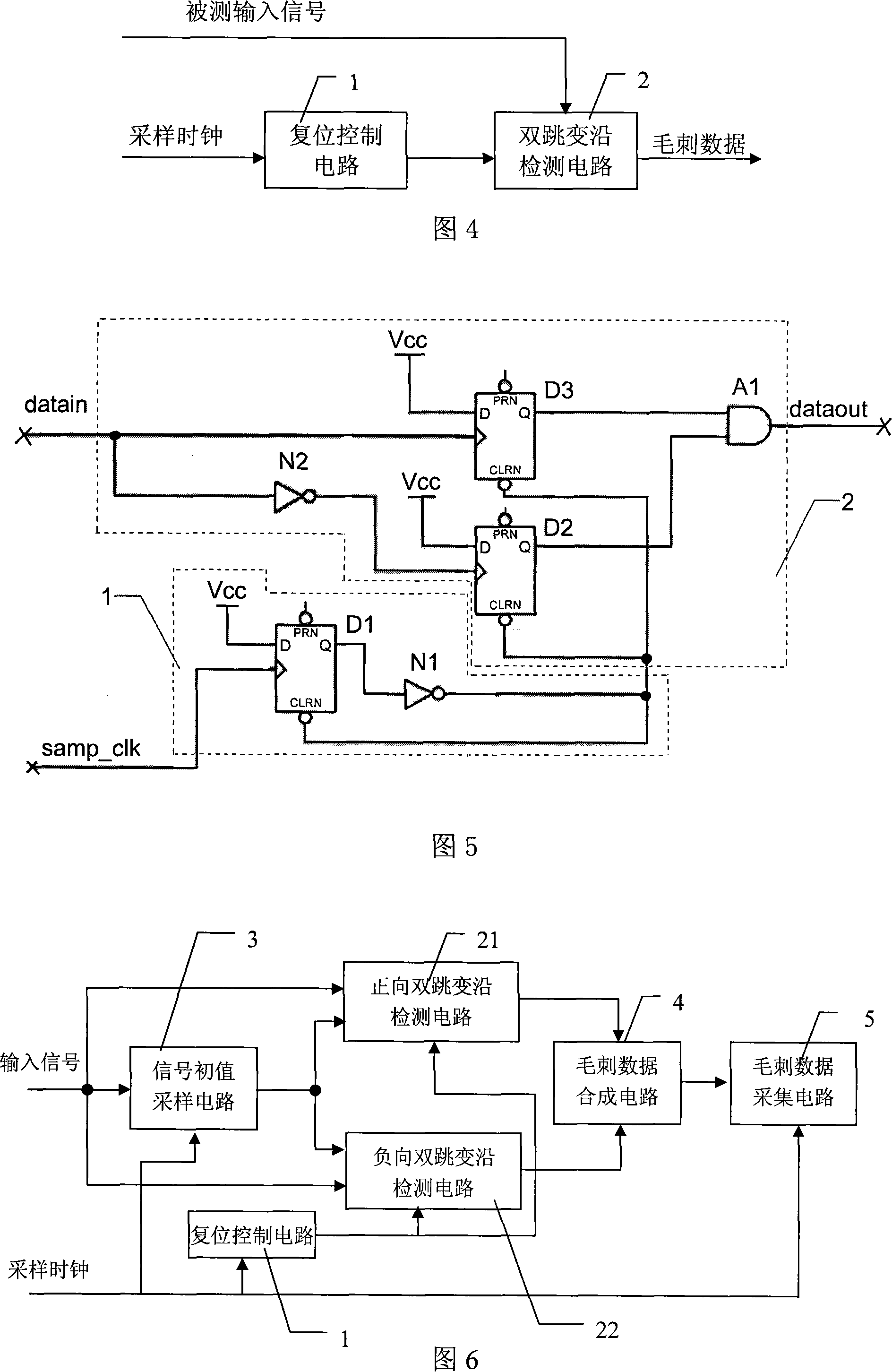
[0027] Fig. 4 is a functional block diagram of the burr detection device of the present invention. In the figure, the glitch detection device includes a double transition edge detection circuit 2 and a reset control circuit 1;

[0028] The double transition edge detection circuit 2 includes a rising edge detection circuit and a falling edge detection circuit. The rising edge detection circuit and the falling edge detection circuit detect the rising edge and falling edge of the input signal under test. If the input signal under ...


PUM


Abstract

The invention discloses a burr detection device that consists of a double bounce inspection circuit and a reset control circuit; if the detected input signals have rising edge or descending edge, the double bounce edge inspection circuit outputs signals that have double bounce edge. The reset control circuit outputs a reset narrow pulse within each sample circle under the action of the clock edge so as to reset each sample circle of the double bounce edge inspection circuit and clean the locked signals that has rising and falling edge. Thus, the double bounce edge inspection circuit has rising edge and falling edge signals only in the sample circle to output signals that has double bounce that is the burr signals. The invention has direct indication for the burr inspection needless of comparing two types of sampling data; at the same time, the level status of the detected input signals does not need time to be inspected. Compared with prior art, the invention is needless of data comparing under the situation of delay, sampling or locking, the circuit is simple and is easy to be realized.

Description

technical field [0001] The invention belongs to the field of digital system testing and analysis, and in particular relates to a burr detection device. Background technique [0002] A logic analyzer is an instrument for analyzing digital system hardware and software, and is one of the most important data domain test instruments. Glitch detection is an important capability of a logic analyzer. A glitch is a narrow pulse whose width is smaller than the specified requirement. In logic analysis, it is considered that a narrow pulse that passes the threshold twice within one sampling clock cycle is a glitch. There are four types of common glitches: positive glitches that appear on the low level of the signal, negative glitches that appear on the high level of the signal, continuous glitches, and glitches that appear on the signal transition edge. Glitch is a false signal caused by interference, transmission delay and competition risk, etc., which will cause the system to work a...

Claims


Application Information

Patent Timeline
IPC IPC(8): H03K5/153H03K5/1534
Inventor 王厚军师奕兵戴志坚田书林李炎俊
Owner UNIV OF ELECTRONIC SCI & TECH OF CHINA
Why Eureka
Try Eureka