Multi-pipe impulse detonating combustion camber and detonation method thereof

A technology of pulse detonation and detonation method, which is applied in the power field and can solve the problems of reduced mixture sensitivity, complicated pulse detonation engine, and increased ignition delay time.

Inactive Publication Date: 2008-03-19
NORTHWESTERN POLYTECHNICAL UNIV
View PDF0 Cites 27 Cited by
  • Summary
  • Abstract
  • Description
  • Claims
  • Application Information

AI Technical Summary

Problems solved by technology

Therefore, pulse detonation engines using detonators are more complex
For the air-breathing pulse detonation engine, due to the dilution of nitrogen in the air, the sensitivity of the mixture is greatly reduced, the energy and power required for direct detona

Method used


Image

  • Multi-pipe impulse detonating combustion camber and detonation method thereof
  • Multi-pipe impulse detonating combustion camber and detonation method thereof
  • Multi-pipe impulse detonating combustion camber and detonation method thereof

Examples


Embodiment 2

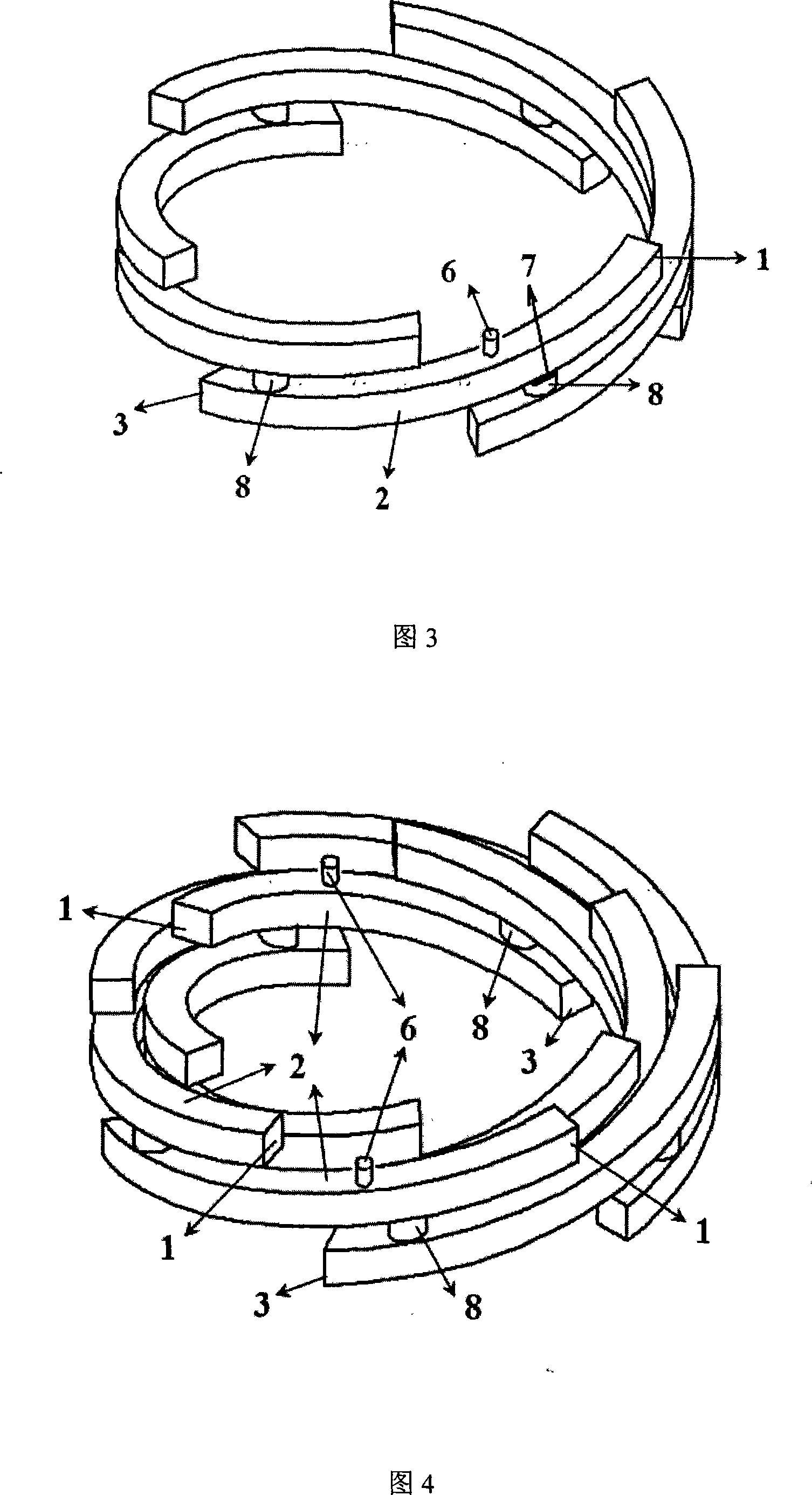
[0023] Device embodiment 2: referring to Fig. 4, it includes two ring-shaped multi-tube pulse detonation combustion chambers, and each ring of multi-tube pulse detonation combustion chambers is respectively connected together by 6 detonation units through the jet propagation pipe 8, Each detonation unit includes a detonation chamber inlet 1, a detonation chamber 2, a detonation chamber outlet 3 and a jet propagation pipe 8, and the jet propagation pipe 8 includes the detonation jet outlet 5 and the lower detonation jet outlet of the upper detonation unit connected together. The detonation jet inlet 4 of the primary detonation unit, the detonation chamber inlet 1 and the detonation chamber outlet 3 are located at both ends of the detonation chamber 2, the detonation chamber inlet 1 is at the most upstream, and the detonation jet inlet 4 is close to and located at the detonation chamber entrance Downstream of 1, the detonation jet outlet 5 is close to and located upstream of the ...


PUM


Abstract

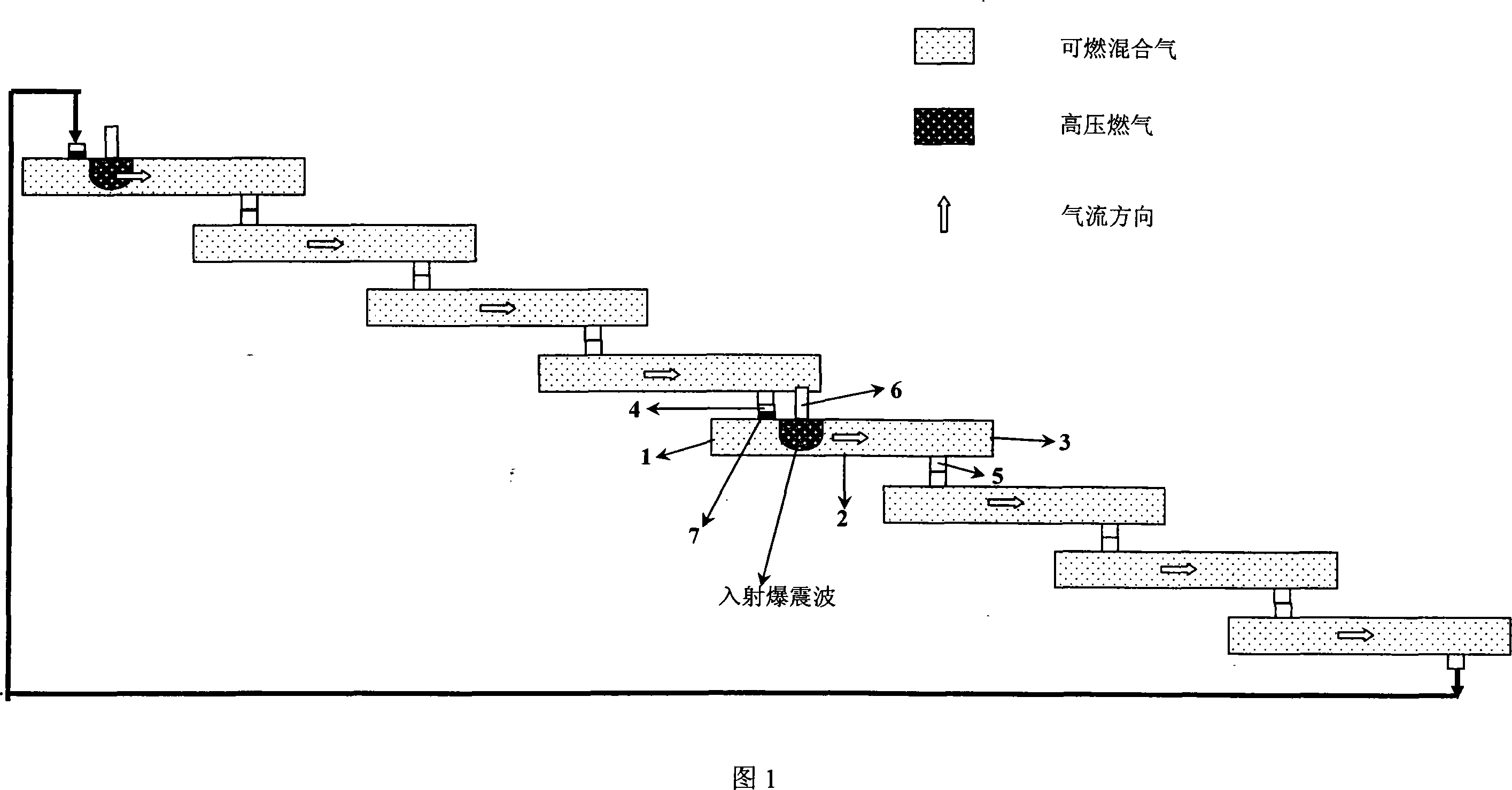
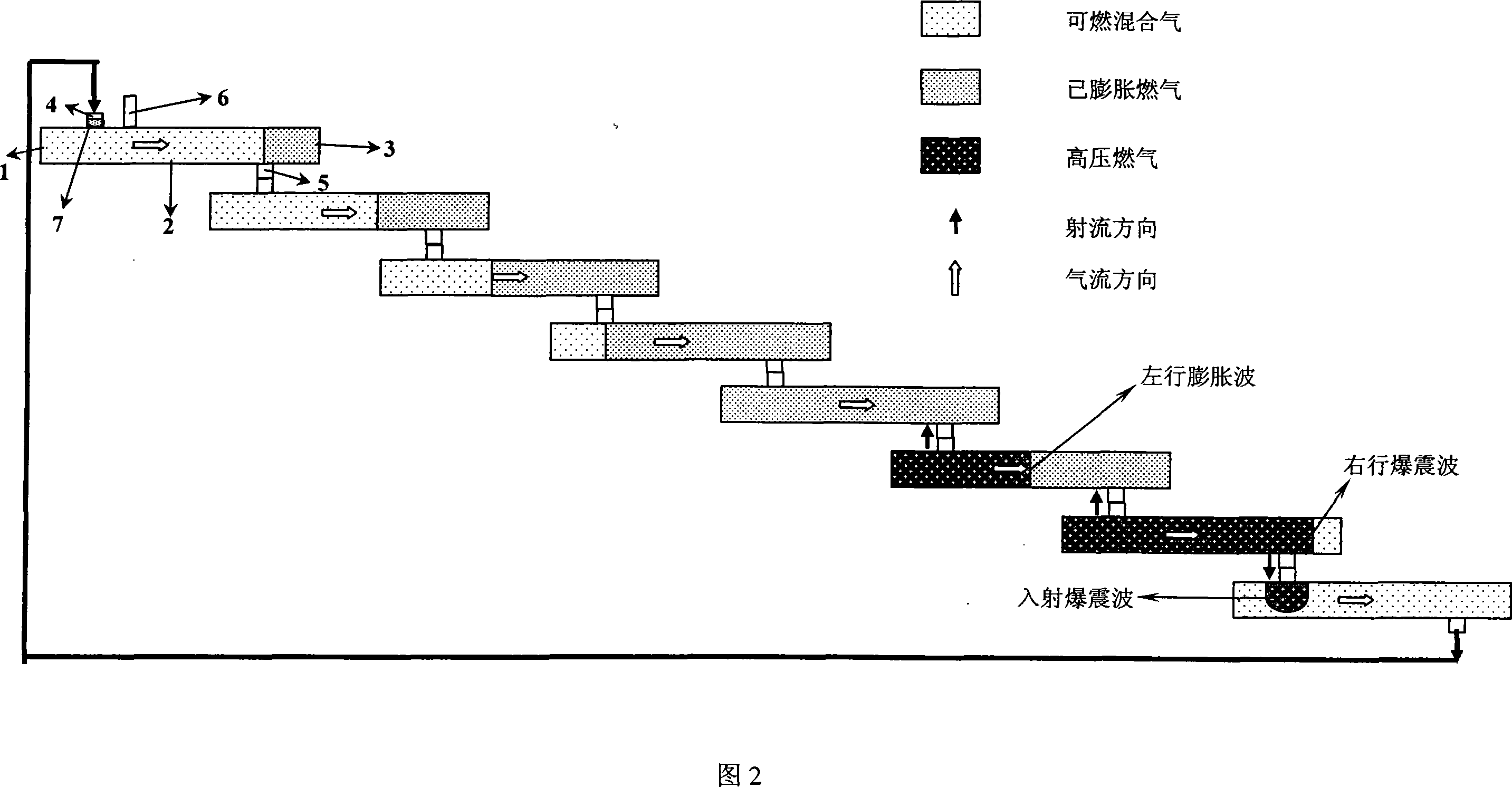
The invention discloses a multi-tube pulse detonation combustion chamber and the detonation method. A detonation chamber inlet opening, a detonation jet flow inlet opening, a detonation jet flow outlet opening and a detonation chamber outlet opening are poditioned in sequence on the detonation chamber, the detonation jet flow outlet opening is connected with the detonation jet flow inlet opening of the adjacent detonation unit, and a plurality of detonation units are connected to form a circular combustion chamber with a plurality of detonation chamber inlet opening and a plurality of detonation chamber outlet opening. The detonation starting device is positioned on the detonation chamber of one of the detonation units. When the detonative gas mixture is filled in the whole detonation chamber 2 through the detonation chamber inlet opening 1 of each detonation unit under the same condition, the detonation starting device 6 of the invention begins to work. The invention realizes the multi-tube pulse detonation combustion chamber with very high working frequency without the dependency of the high energy and high frequency ignition system, and the invention can be used to replace the main combustion chamber or booster combustion chamber of the existing gas-turbine engine, or the combustion chamber of the rotating ramjet engine.

Description

technical field [0001] The invention relates to the field of power, in particular to a pulse detonation combustion chamber and its detonation method. Background technique [0002] There are two kinds of combustion waves in nature: one is deflagration wave and the other is detonation wave. The detonation wave propagates toward the unburned mixture at a speed of several kilometers per second. A detonation wave is essentially a shock wave followed by a combustion wave. The detonation wave can generate extremely high gas pressure (greater than 15 to 55 atmospheres) and gas temperature (greater than 2800K). Due to the extremely fast propagation speed of the detonation wave, the subsequent combustion process can be regarded as a constant volume combustion process, so its combustion efficiency very high. Due to the high efficiency of the pulse detonation cycle, and the pulse mode of operation, this makes it very attractive for propulsion systems. When the working frequency reac...

Claims


Application Information

Patent Timeline
IPC IPC(8): F02K9/62F02K9/95
Inventor 李牧严传俊
Owner NORTHWESTERN POLYTECHNICAL UNIV
Why Eureka
Try Eureka