
Vehicle electronic brake system actuator

An electronic parking brake and actuator technology, applied in the direction of brake actuator, brake type, brake components, etc., can solve the problems of cumbersome processing and assembly, achieve good size consistency, low labor intensity, and save driving effect of room space

Inactive Publication Date: 2010-06-02
ZHEJIANG ASIA PACIFIC MECHANICAL & ELECTRONICS
View PDF5 Cites 3 Cited by
  • Summary
  • Abstract
  • Description
  • Claims
  • Application Information

AI Technical Summary

Problems solved by technology

The above three forms all use the addition of multiple necessary parts to realize the automatic adjustment of the brake clearance, so the processing and assembly are cumbersome

Method used


Image

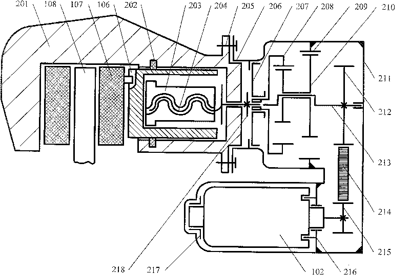
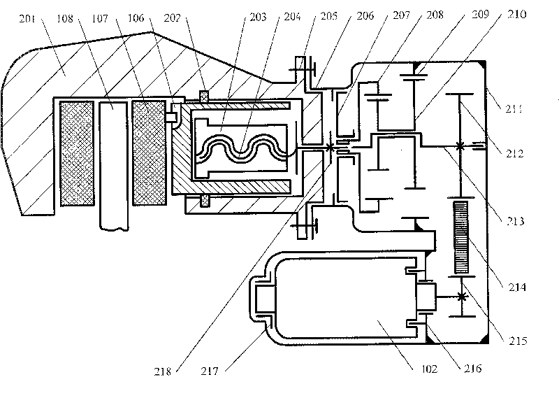
  • Vehicle electronic brake system actuator
  • Vehicle electronic brake system actuator
  • Vehicle electronic brake system actuator

Examples


Embodiment Construction

[0017] The present invention will be further described below in conjunction with the accompanying drawings and specific embodiments.

[0018] like figure 1 Shown is the transmission block diagram of the actuator of the vehicle electronic parking brake system of the present invention. Battery 101, DC motor 102, synchronous belt transmission mechanism 103, involute small tooth difference planetary gear transmission mechanism 104, sliding screw transmission mechanism 105, piston 106, brake block assembly 107 and brake disc 108 sequentially transmit energy downwards .

[0019] like figure 2 Shown is a schematic diagram of the structure and principle of the actuator of the vehicle electronic parking brake system of the present invention. The invention includes a transmission device and a brake caliper assembly. The front casing 206 and the rear casing 211 of the transmission device are connected by fixed sealing to form a semi-closed casing. The casing containing the rest of t...


PUM


Abstract

The invention discloses an implementing mechanism of a vehicle electronic parking brake system. The invention comprises a transmission device and a brake clipping caliper assembly. After the output ofthe direct current motor in the transmission device is performed with speed reduction and torque increase via a synchronization belt transmission device and a involute few tooth difference planetarytransmission device, the rotation motion is transferred into a straight line motion through a sliding helical transmission mechanism, and a braking disc is braked through the method that a piston anda braking block assembly are pushed by a screw sleeve. The circumferential freedom degree of the piston is limited by the braking block assembly, and the circumferential and the racial freedom degreesof the screw sleeve are respectively limited by a piston non-round hole and a blocking ring. The screw sleeve and a screw rod adopt self locking thread matching, to guarantee the parking braking to be secure and reliable. Compared with the implementing mechanism of the traditional vehicle rear wheel parking braking system, the invention has the advantages that the driving cab space is saved, thelabor intensity of the driver is reduced, the parting braking is more secure and reliable, and the invention is convenient for adopting intelligent control and integrating other functions.

Description

technical field [0001] The invention relates to a vehicle parking brake system, in particular to an actuator of a vehicle electronic parking brake system. Background technique [0002] The rear wheel parking brake system of the vehicle is mainly composed of the parking brake, the transmission device and the control device, and mainly has the following three forms: 1. The rear wheel drum brake used for the service brake is also used as the parking brake. The brake pull arm, brake cable, etc. that are connected in sequence to the drum brake are used as transmission devices; 2. The rear wheel brake caliper assembly used for driving brake also serves as a parking brake, and the screw rod installed in the brake caliper , screw sleeves and external brake arms and brake cables connected in sequence as transmission devices; 3. A drum brake is installed separately in the rear wheel brake disc as a parking brake, and the drum brake connected in sequence Brake pull arms, brake cables,...

Claims


Application Information

Patent Timeline
Patent Type & Authority Patents(China)
IPC IPC(8): F16D65/34F16D65/28
Inventor 郭立书张正兵
Owner ZHEJIANG ASIA PACIFIC MECHANICAL & ELECTRONICS
Learn More