
Insulation layer and semiconductor conducting layer aligning error electrical testing structure in micro-electro-mechanical system
A micro-electromechanical system and alignment error technology, which is applied in semiconductor/solid-state device testing/measurement, microstructure technology, electric solid-state devices, etc., can solve problems such as alignment error extraction, achieve consistent measurement methods, simple test equipment, The effect of simple test methods
- Summary
- Abstract
- Description
- Claims
- Application Information
AI Technical Summary
Problems solved by technology
Method used
Image


Examples
Embodiment Construction
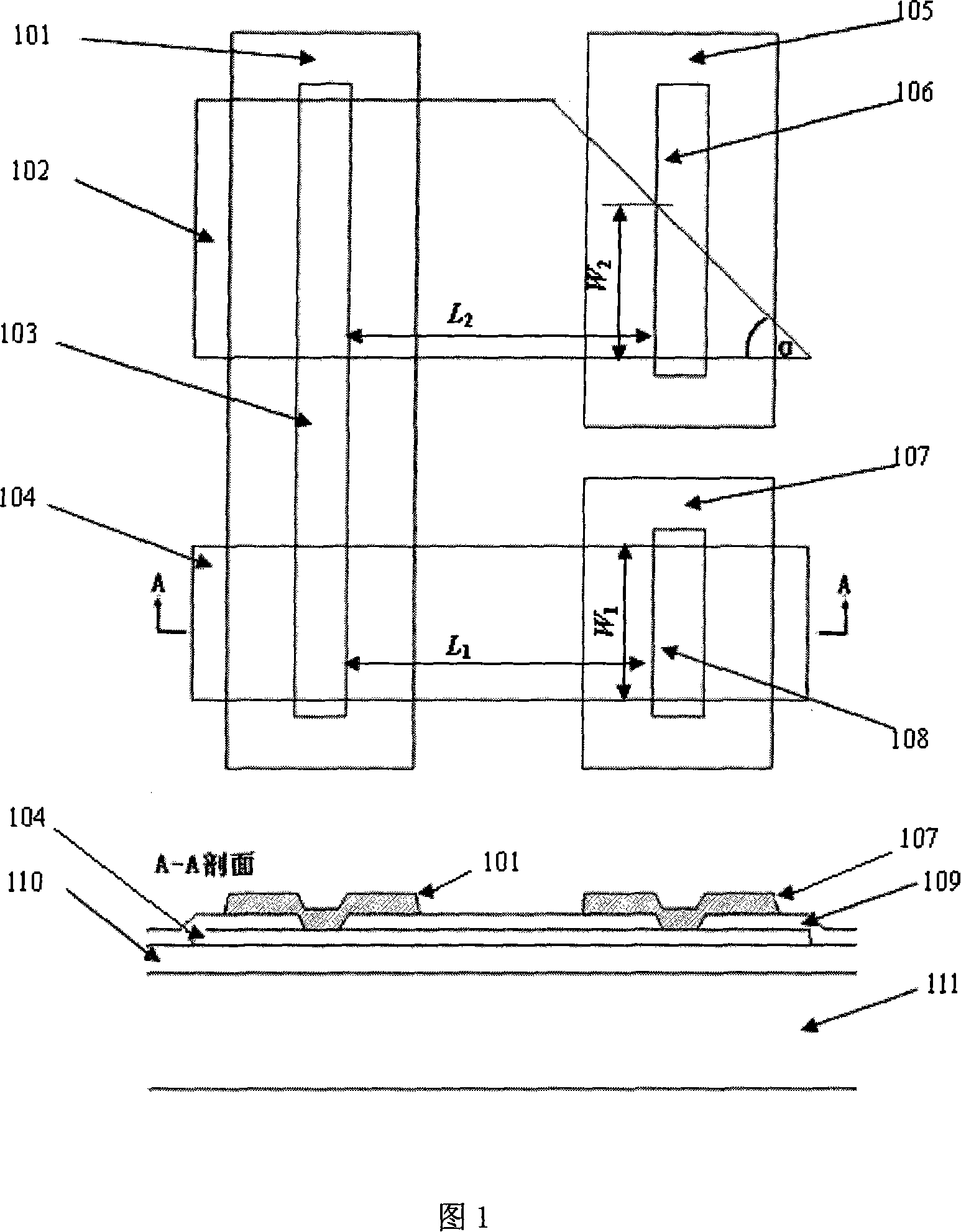
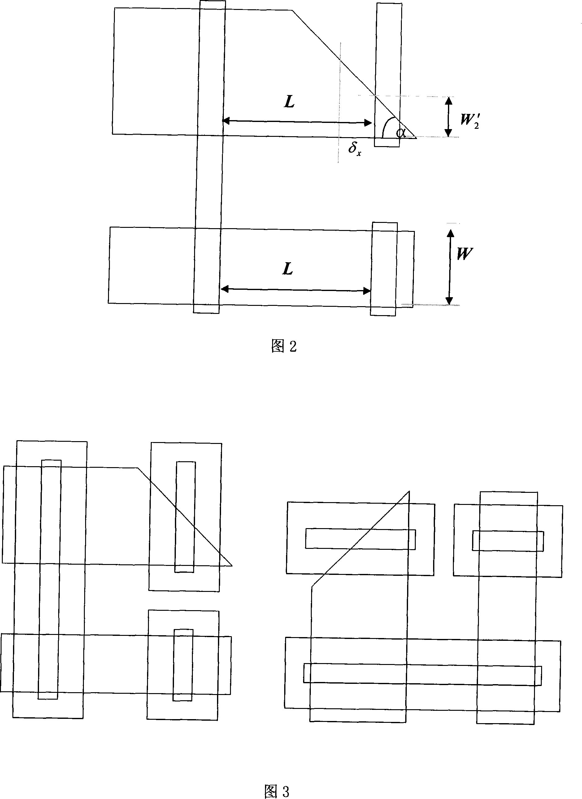
[0014] Fig. 1 shows the test structure graph of the pattern error of the insulation layer pattern aligned with the semiconductor conductive layer pattern, and the cross-sectional structure of the structure is also shown in the figure. In the test structure, 102 is a trapezoid and 104 is a rectangle. The material of these two patterns is a semiconductor material layer, which can be polysilicon 1 or polysilicon 2. They all have conductivity due to doping, of course, they must There is resistance. 103, 106, 108 are lead wire holes opened on the insulating layer 109, 101, 105, 107 are strip-shaped metal layers, covered on the holes of the insulating layer, and its size is greater than the size of the hole, so as to ensure the connection between the metal pattern and the insulating layer. The hole can still be completely covered when the layer pattern is offset. 110 is an insulating material, usually silicon nitride. 111 is a silicon substrate. The semiconductor conductive layer...
PUM
 Abstract
Description
Claims
Application Information