Elevator door apparatus

A technology for elevator doors and elevators, which is used in elevators, transportation and packaging, elevators and other directions in buildings, and can solve the problems that the miniaturization of the motor cannot be realized, the life of the belt cannot be prolonged, and the burden becomes larger.

Inactive Publication Date: 2008-03-19
MITSUBISHI ELECTRIC CORP
View PDF1 Cites 4 Cited by
  • Summary
  • Abstract
  • Description
  • Claims
  • Application Information

AI Technical Summary

Problems solved by technology

[0004] However, in conventional elevator door devices, the door is moved by the driving force of a single motor, so the size of the motor itself increases.
[0005] In addition, even if the pulleys are independently rotated by the driving force of the two motors, for example, if the entrance and exit width is large, the distance between the pulleys will increase, so the tension of the belt will also increas

Method used


Image

  • Elevator door apparatus
  • Elevator door apparatus
  • Elevator door apparatus

Examples


Embodiment approach 1

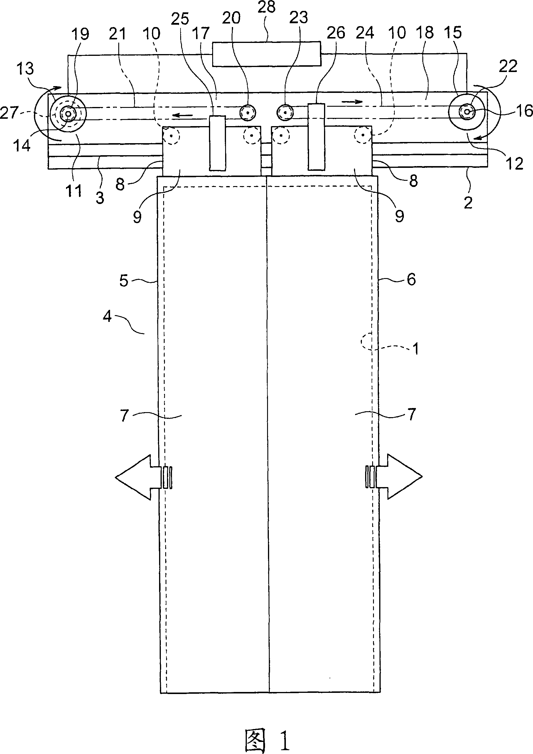
[0017] Fig. 1 is a front view showing an elevator door apparatus according to Embodiment 1 of the present invention. In FIG. 1 , a car doorway (elevator doorway) 1 is provided on a car (not shown). In addition, a hanger case 2 provided on the upper part of the car entrance 1 is fixed to the car.

[0018] A hanging door rail (support rail) 3 extending in the width direction of the car doorway 1 is fixed to the hanging door box 2 . An elevator door 4 for opening and closing the car doorway 1 is suspended on the hanging door rail 3 .

[0019] The elevator door 4 has a first door 5 and a second door 6 movable in the width direction of the car doorway 1 . The first door 5 and the second door 6 are arranged side by side with each other in the width direction of the car doorway 1 . The car doorway 1 is closed when the first door 5 and the second door 6 contact each other, and is opened when the first door 5 and the second door 6 are separated.

[0020] The first door 5 can be pos...

Embodiment approach 2

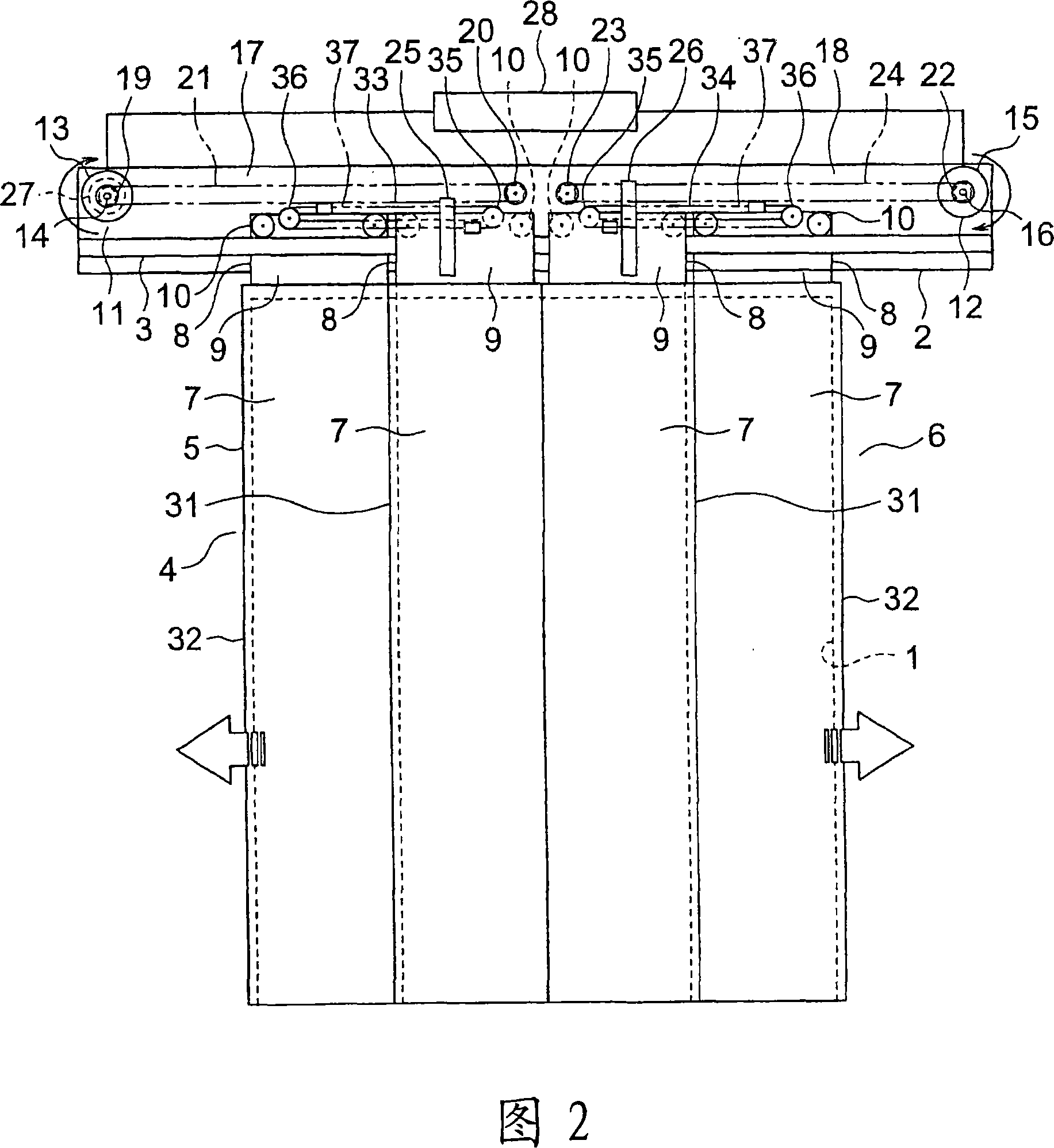
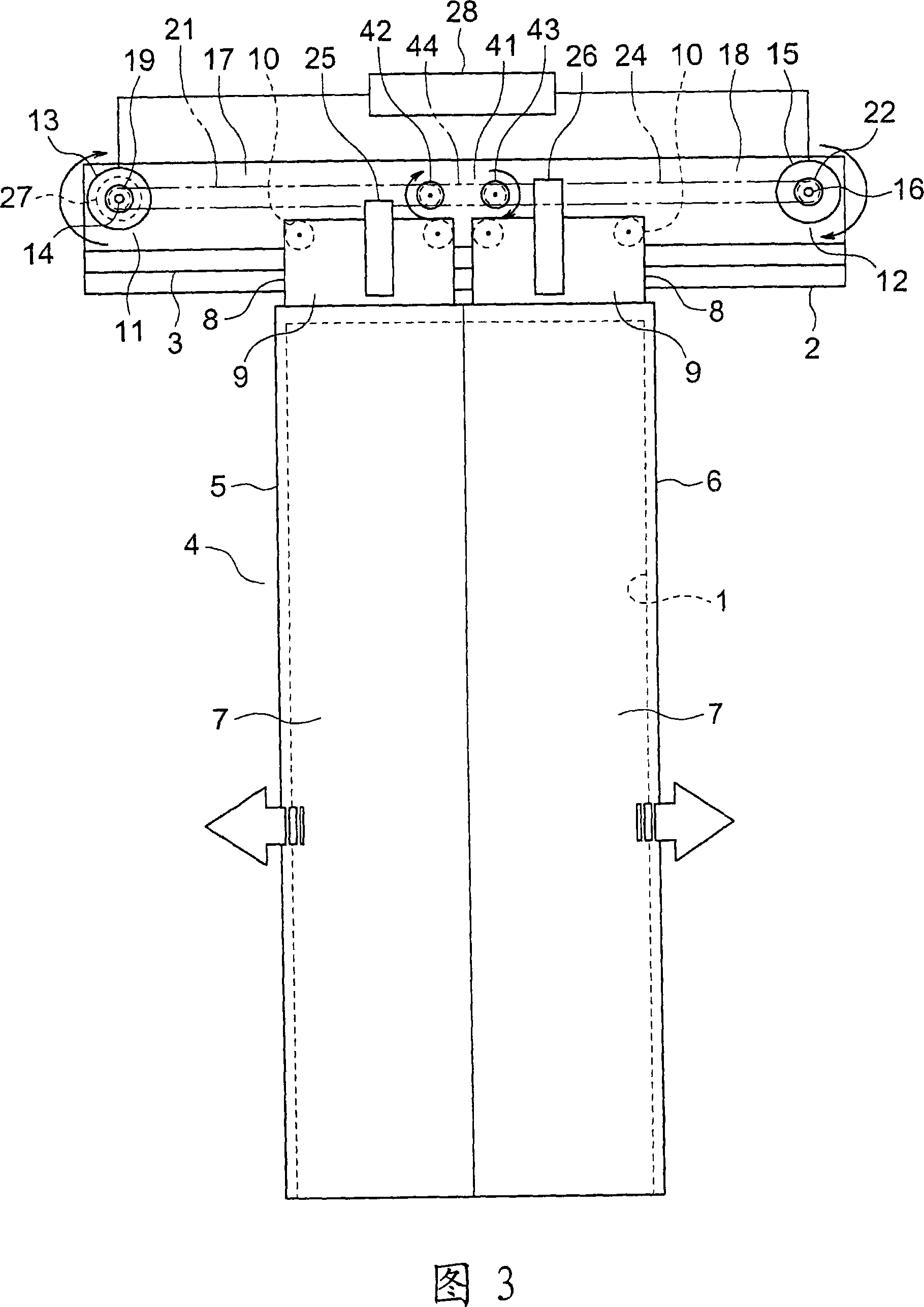
[0049] Fig. 3 is a front view showing an elevator door device according to Embodiment 2 of the present invention. In addition, FIG. 4 is a plan view showing a part of the elevator door apparatus of FIG. 3 . In the drawing, an interlocking mechanism 41 for synchronizing the moving speed of the first door 5 and the moving speed of the second door 6 is provided between the first power transmission mechanism 17 and the second power transmission mechanism 18 .

[0050] The interlocking mechanism 41 has: a first interlocking pulley 42 that rotates integrally with the first driven pulley 20; a second interlocking pulley 43 that rotates integrally with the second driven pulley 23; The ring-shaped interlocking bar body 44 between the movable pulleys 43.

[0051] The first interlocking pulley 42 is provided coaxially with the first driven pulley 20 , and the second interlocking pulley 43 is provided coaxially with the second driven pulley 23 . The bar body 44 for interlocking moves ci...

Embodiment approach 3

[0055] Fig. 5 is a front view showing an elevator door device according to Embodiment 3 of the present invention. In the figure, the encoder 27 which generates the signal corresponding to the rotation of the 1st rotating shaft 14 is provided in the 1st door driver 11 as a 1st position detector. Moreover, the encoder 51 which generates the signal corresponding to the rotation of the 2nd rotation shaft 16 is provided in the 2nd door driver 12 as a 2nd position detector.

[0056] Information from the respective encoders 27 and 51 is input to the door control device 28 . The door control device 28 has: a first door control unit 52 that controls the first door driver 11 based on information from the encoder 27; and a second door control unit 53 that controls the second door driver 12 based on information from the encoder 51. . That is, the door control device 28 has the 1st door control part 52 and the 2nd door control part 53 which control the 1st door drive device 11 and the 2n...


PUM


Abstract

The present invention provides an elevator door device, which has: an elevator door including a first door and a second door; a first door driving device and a second door driving device respectively having a first rotating shaft and a second rotating shaft; The first power transmission mechanism that moves the first door by the rotation of the first rotation shaft; the second power transmission mechanism that moves the second door by the rotation of the second rotation shaft; the signal that generates a signal corresponding to the rotation of the first rotation shaft a position detector; and a door control device for controlling the second door driver so that the rotation of the second rotation shaft follows the rotation of the first rotation shaft based on the information from the position detector. Thereby, the moving speeds of the first door and the second door can be synchronized based on information from one position detector.

Description

technical field [0001] The invention relates to an elevator door device for opening and closing elevator entrances and exits. Background technique [0002] Conventionally, an elevator door apparatus has been proposed in which an outer rotor type motor is disposed inside one of a pair of pulleys for downsizing. A belt is wound between a pair of pulleys. A door for opening and closing the entrance is connected to the belt. When one pulley is rotated by the driving force of the electric motor, the belt moves in a circle and the other pulley also rotates. Thereby, a door moves, and an entrance is opened and closed (refer patent document 1). [0003] Patent Document 1: Japanese Patent Laid-Open No. 2001-226058 [0004] However, in the conventional elevator door apparatus, the door is moved by the driving force of a single motor, and therefore the size of the motor itself is increased. [0005] Also, even if the pulleys are independently rotated by the driving force of the tw...

Claims


Application Information

Patent Timeline
IPC IPC(8): B66B13/14B66B13/08B66B3/00
CPCB66B13/08B66B13/14B66B3/00
Inventor 小泉喜彦藤木雄
Owner MITSUBISHI ELECTRIC CORP
Why Eureka
Try Eureka