Exhaust gas heat exchanger, in particular an exhaust gas cooler for exhaust gas recirculation in a motor vehicle

A technology of exhaust gas recirculation and exhaust gas cooler, which can be used in exhaust gas recirculation, heat exchange equipment, heat exchanger shells, etc., and can solve problems such as high space requirements

Active Publication Date: 2008-03-19
BEHR GMBH & CO KG +1
View PDF6 Cites 9 Cited by
  • Summary
  • Abstract
  • Description
  • Claims
  • Application Information

AI Technical Summary

Problems solved by technology

This results in a higher space requirement compared to a

Method used


Image

  • Exhaust gas heat exchanger, in particular an exhaust gas cooler for exhaust gas recirculation in a motor vehicle
  • Exhaust gas heat exchanger, in particular an exhaust gas cooler for exhaust gas recirculation in a motor vehicle
  • Exhaust gas heat exchanger, in particular an exhaust gas cooler for exhaust gas recirculation in a motor vehicle

Examples


Embodiment Construction

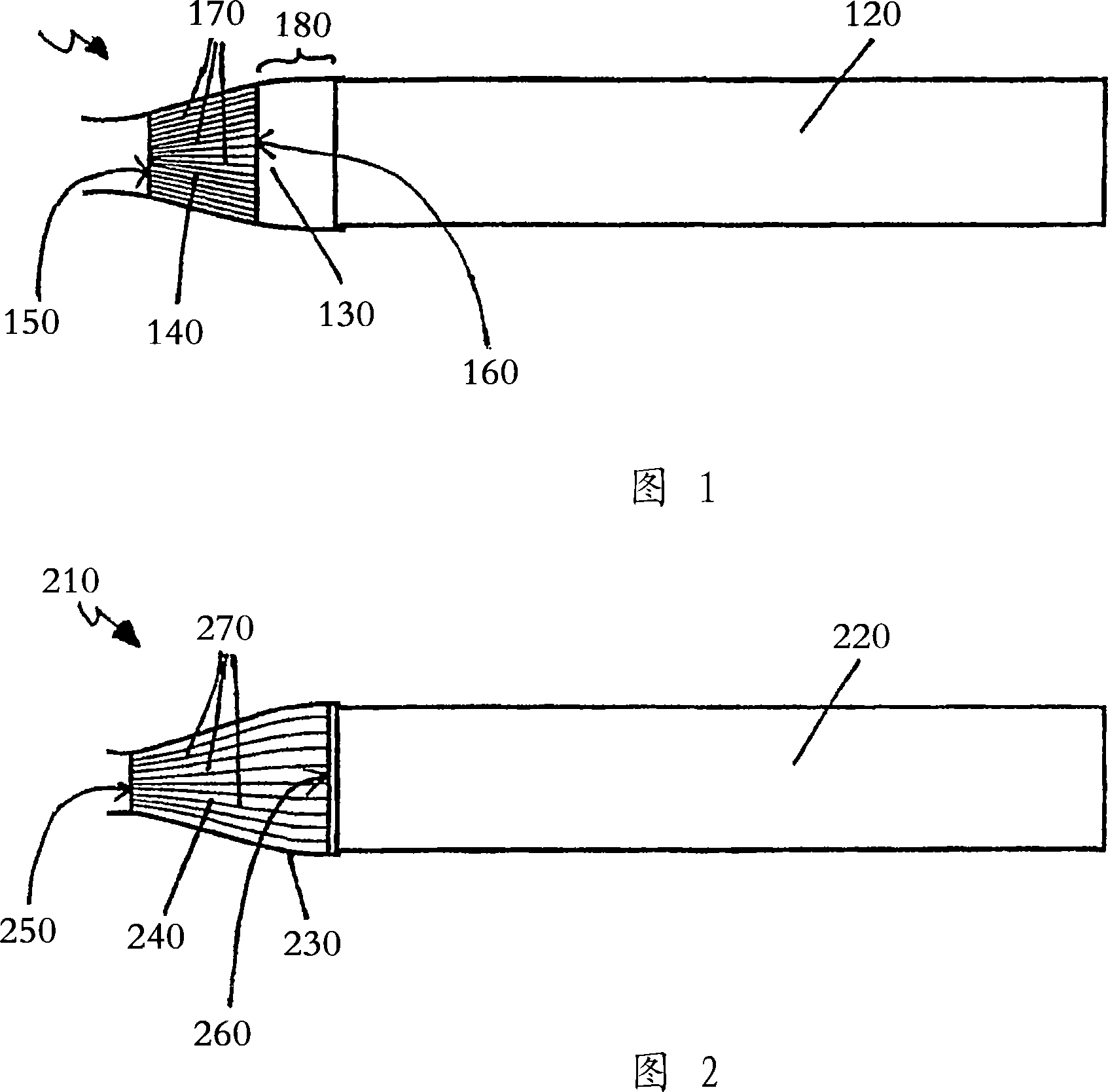
[0027] FIG. 1 shows a heat exchanger 110 with heat exchanger channels, not specifically shown, which are combined to form a heat exchanger assembly 120 , for example a tube bundle. The inflow side channel distribution chamber 130 of the heat exchanger channel is arranged in the distribution chamber with a flow guiding device 140 having a flat exhaust gas inlet surface 150 and a flat exhaust gas inlet surface 150 . Parallel exhaust gas outlet surfaces 160 . The distribution chamber 130 is welded or soldered to the heat exchanger assembly 120, for example.

[0028] A plurality of flow passages 170 extend from the exhaust gas intake face 150 to the exhaust gas discharge face 160 . The flow channels 170 are inclined relative to one another, so that the cross-section of the exhaust gas flow entering the exhaust gas heat exchanger 110 from the left in FIG. 1 is enlarged by means of the flow guiding device, wherein the exhaust gas flow is preferably additionally homogenized here.

...


PUM


Abstract

The invention relates to an exhaust gas heat exchanger, in particular, to an exhaust gas cooler for exhaust gas recirculation in a motor vehicle comprising heat exchanging conduits which are passed through by exhaust gases, surrounded by a coolant and linked to a distributing and/or collecting chambers comprising a flux guiding device which is provided with the exhaust gas input and output sides and a plurality of channels extending therebetween and inclined to each other.

Description

technical field [0001] The invention relates to an exhaust gas heat exchanger according to the preamble of claim 1 , in particular an exhaust gas cooler for recirculation of exhaust gases in a motor vehicle. Background technique [0002] The exhaust gas heat exchanger is used on the one hand to heat the coolant for heating purposes and on the other hand to cool the exhaust gas, ie it is used as an exhaust gas cooler in the recirculation of the motor vehicle. Exhaust gas recirculation (abbreviated AGR) is known to reduce losses and increase heat dissipation. An exhaust gas recirculation system is known, for example, from DE-C19906401. A problem with such exhaust gas heat exchangers, in particular exhaust gas coolers, is that soot deposits occur in the diesel exhaust gas in the exhaust gas ducts of the exhaust gas cooler. Therefore, it is proposed in EP-A677715 and DE-A19540683 for coolers to provide swirling devices in the exhaust gas line which prevent soot deposits in the...

Claims


Application Information

Patent Timeline
IPC IPC(8): F28F27/02F02M25/07
CPCF01N3/2892F02M25/074F28F9/02Y02T10/16F01N3/02F28F9/0268F02B37/00Y02T10/20F02M25/0737Y02T10/121F02M25/0735F02M25/0707F02B29/0406F28F2009/029F02M26/05F02M26/30F02M26/32F02M26/35Y02A50/20Y02T10/12F28F27/02
Inventor 罗尔夫·布鲁克彼得·格斯凯斯乌尔里克·莫彻詹斯·拉克威德安德烈亚斯·奇德
Owner BEHR GMBH & CO KG
Why Eureka
Try Eureka