Thread feeding automatic riveting stamping technology

A riveting stamping machine, automatic technology, applied in the stamping field of terminals, can solve the problems of high failure rate and low production efficiency of shrapnel

Inactive Publication Date: 2008-03-26
东莞市中一合金科技有限公司
View PDF0 Cites 10 Cited by
  • Summary
  • Abstract
  • Description
  • Claims
  • Application Information

AI Technical Summary

Problems solved by technology

[0003] The purpose of the present invention is to provide a wire-feeding automatic riveting and stamping process that saves procedures, is fast in production speed

Method used


Image

  • Thread feeding automatic riveting stamping technology
  • Thread feeding automatic riveting stamping technology
  • Thread feeding automatic riveting stamping technology

Examples


Embodiment Construction

[0024] In order to further disclose the present invention, it will now be described in conjunction with FIGS. 3 , 4 , 5 , 6 , 7 , and 8 . It includes the following steps:

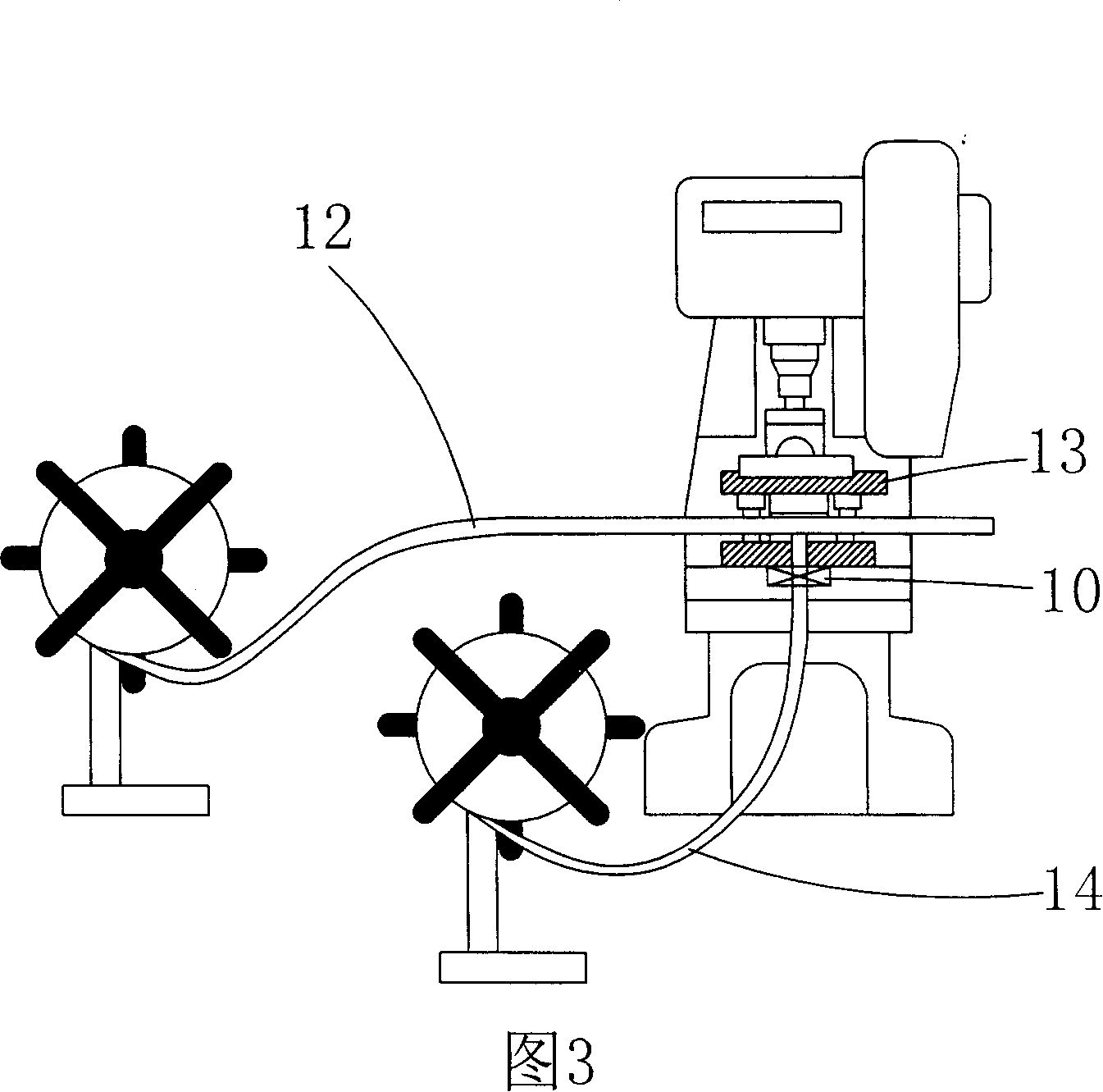
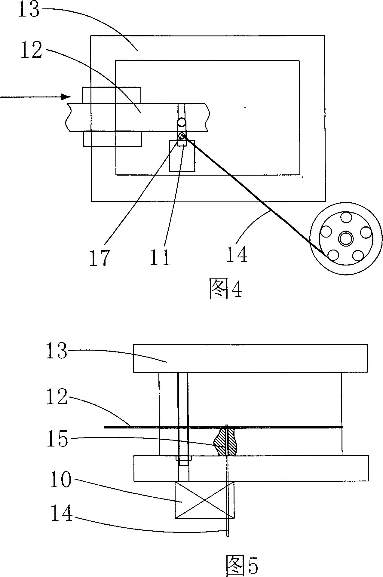
[0025] a. Install a miniature wire feeding wheel mechanism 10 and a slider wire trimming device 11 on the stamping die;

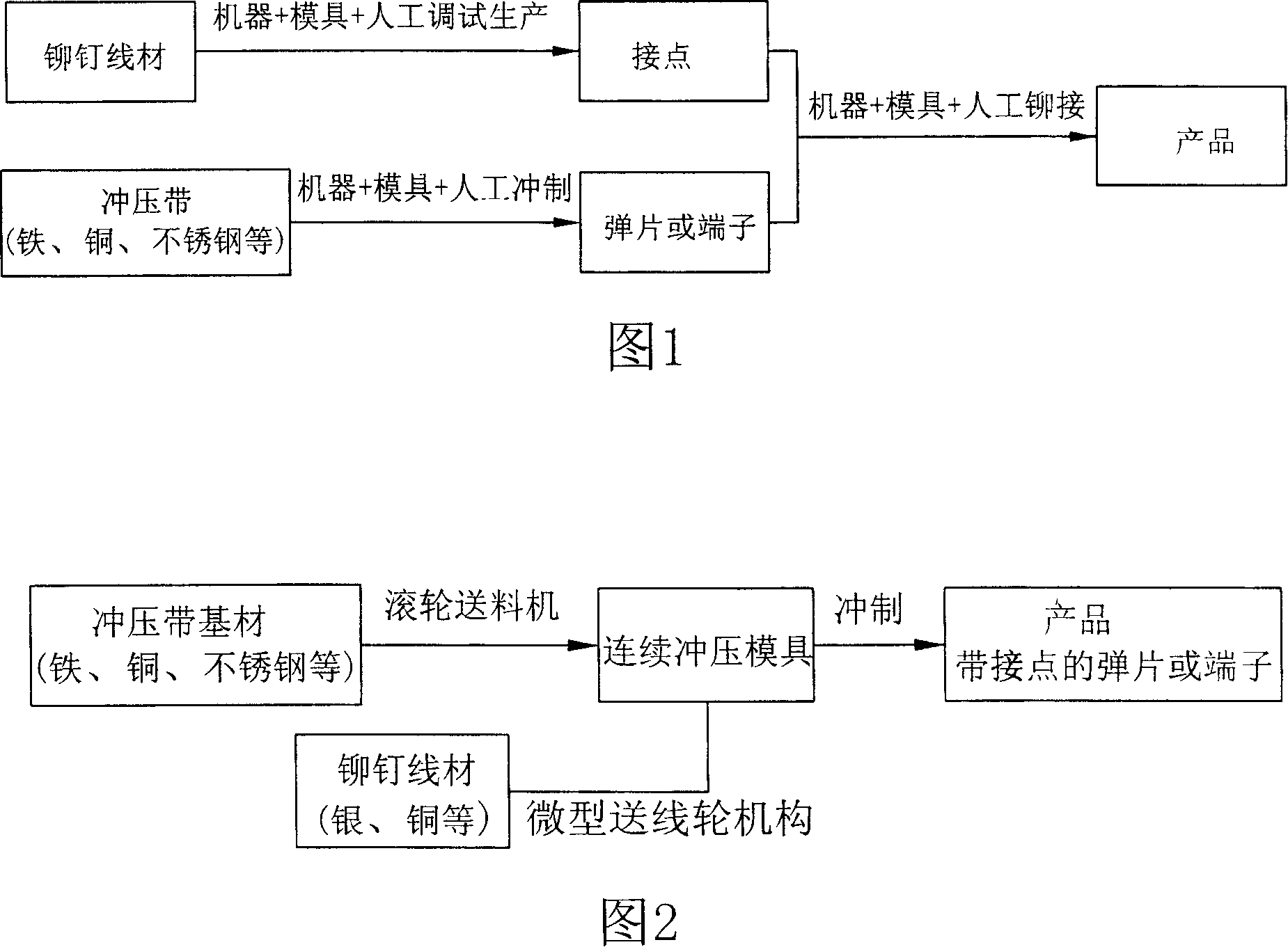
[0026] b. The stamping belt base material 12 is transported into the stamping die 13 by the roller feeding mechanism of the punching machine, and the rivet wire 14 is transported into the stamping die 13 by the micro-feeding wheel mechanism 10, and the rivet wire 14 is sent from the bottom of the stamping die 13, And make the end of the rivet wire 14 perpendicular to the stamping strip substrate 12;

[0027] c. A plurality of stamping cavities are formed on the stamping die 13 of the present invention. During the conveyance process of each stamping strip base material 12, each part of the stamping strip base material 12 that will be stamped and bloomed into a terminal passes through eac...


PUM


Abstract

The present invention relates to punching technology, and is especially one automatic wire feeding, riveting and punching process. By means of using punching die with several punching die cavities for simultaneous punching formations on the base material, one miniature wire feeding wheel mechanism for automatic wire feeding and one wire cutting block mechanism for cutting off wire, the present invention completes one automatic wire feeding, riveting and punching process including terminal punching, rivet punching and riveting in one punch to produce terminal with joint. The present invention has less production steps, low cost, high production speed and high riveting quality, and is suitable for batch production.

Description

Technical field: [0001] The invention relates to the technical field of stamping for processing terminals with contacts, in particular to an automatic stamping process for wire feeding riveting. Background technique: [0002] At present, the terminals and shrapnel with contacts are processed. The rivets, shrapnel, and terminals are stamped separately and then riveted through a stamping die or manually. As shown in Figure 1, the wire is stamped into a rivet in a mold on a special machine tool. In the mold of another machine tool, the stamping strip is punched into shrapnel or terminals, and then the rivets are riveted on the shrapnel or terminals through the stamping die on the third machine tool, and finally the shrapnel or terminals with contacts are formed. At present, there are also Manual riveting processing, which is directly riveting the rivet to the shrapnel or terminal by hand. The current processing method has many processing procedures and requires many machine to...

Claims


Application Information

Patent Timeline
IPC IPC(8): B23P13/00B23P23/00B21D43/09B21D35/00B21D37/10B21G3/32B21G3/18B21J15/00
Inventor 陈启荣
Owner 东莞市中一合金科技有限公司
Why Eureka
Try Eureka