Pneumatic shifting device

A technology of pneumatic shifting and mounting holes, applied in transmission control, components with teeth, belts/chains/gears, etc., can solve the problems of poor maintainability and assembly, low efficiency, frequent manipulation, etc. The layout, the overall structure is simple, and the inspection and maintenance are convenient.

Inactive Publication Date: 2008-03-26
ZHONGNAN TRANSMISSION MACHINERY FACTORY CHANGSHAAVIATION IND
View PDF1 Cites 9 Cited by
  • Summary
  • Abstract
  • Description
  • Claims
  • Application Information

AI Technical Summary

Problems solved by technology

[0002] At present, most of the transmission shifting actuators in the field of automobile manufacturing are mechanical manual shifting. Its typical structure is to realize the synchronizer shifting through the manual lever to drive the connecting rod and the shift fork. The main disadvantages are frequent manipulation and high labor intensity.
The typical structure of the hydraulic transmission automatic shift transmission (AT) shift actuator used in some high-end passenger cars is to realize the gear shift by controlling the complex hydraulic system and hydraulic friction clutch through the electronic valve. High consumption, poor maintainability and assembly
[0003] The utility model patent with the patent number ZL200520066894.0 discloses a pneumatic shift device for an automobile transmission. The air increases the pressure of the left cavity or the right cavity, and pushes the piston ring to move axially to the right or left in the sealed cavity, thereby driving the shift fork shaft to move accordingly to realize the automatic shifting of the transmission. The neutral position of the transmission is automatically pushed back by the gear selection balance springs respectively provided in the left cavity and the right cavity. The main defect is that after the compressed air supply of the gear position control cylinder is terminated, the gear selection The balance spring automatically pushes back, and the car is prone to gear loss during vibration and movement

Method used


Image

  • Pneumatic shifting device
  • Pneumatic shifting device
  • Pneumatic shifting device

Examples


Embodiment Construction

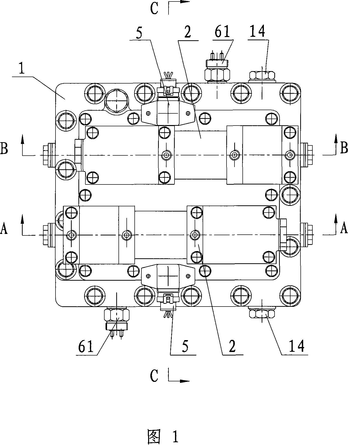
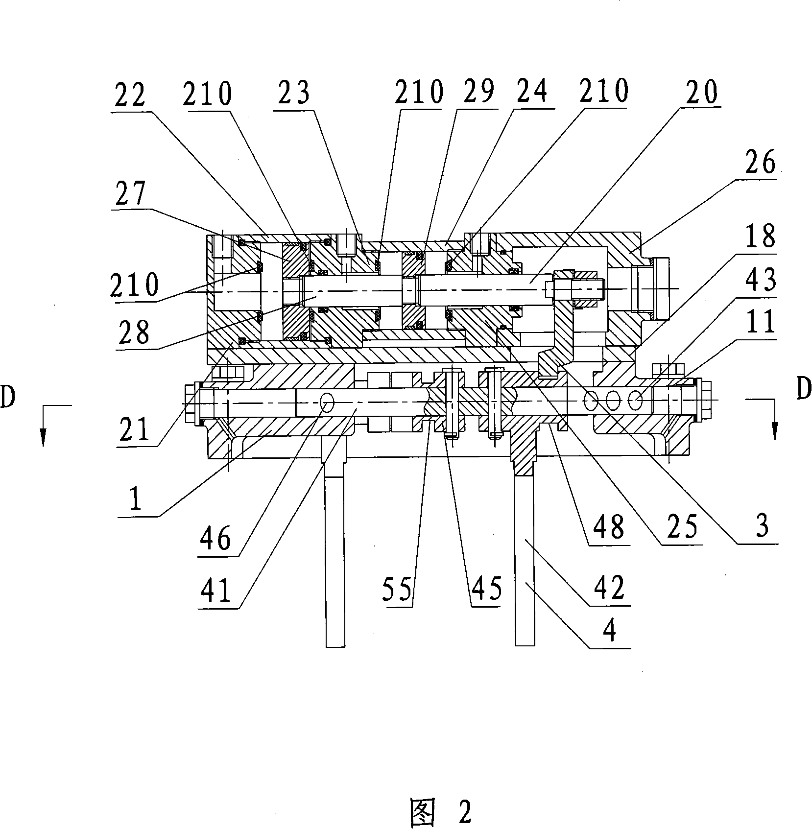
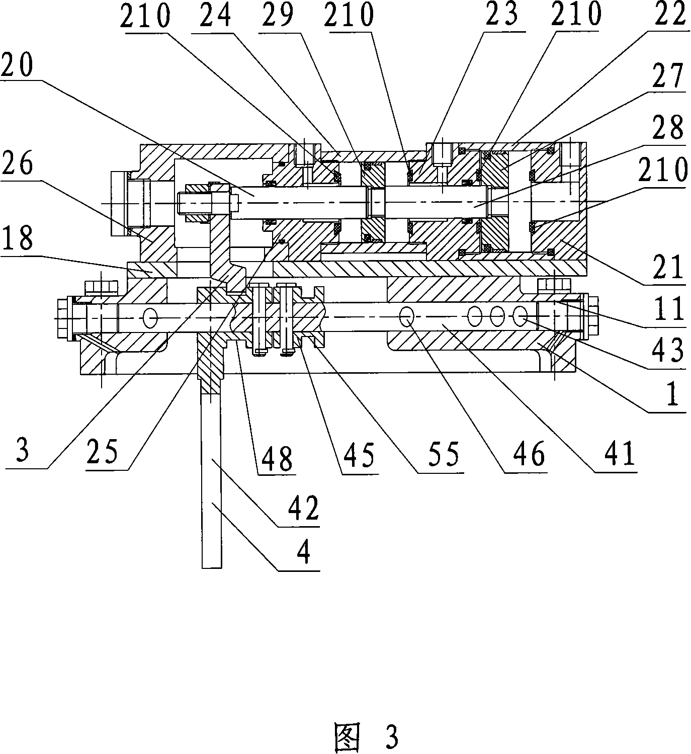
[0048]As shown in Figures 1 to 5, a pneumatic shifting device of the present invention includes a housing 1, two actuators 4 are installed in the housing 1, a connecting plate 18 is installed on one side of the housing 1, and the connecting plate 18 is equipped with two drive cylinders 2 controlled by the electromagnetic valve control device, and the two drive cylinders 2 are respectively the first drive cylinder and the second drive cylinder. Each driving cylinder 2 comprises a cover plate 21, a large cylinder block 22, a connection seat 23, a small cylinder block 24, a supporting cover 25 and a cylinder head 26 connected one by one, and the cover plate 21, the large cylinder block 22 and the connection seat 23 encircle a large cavity body, a large piston ring 27 is set in the large cavity, a large piston ejector rod 28 fixedly connected with the large piston ring 27 is set in the connecting seat 23, and a small cavity is surrounded by the connecting seat 23, the small cylinde...


PUM


Abstract

The pneumatic gear shifting apparatus includes one casing with one executing mechanism; and one driving cylinder beside the casing and comprising one cover plate, one large cylinder body, one connecting seat, one small cylinder body, one support cover and one cylinder cover. The large cylinder body and the connecting seat enclose one large cavity with one large piston ring inside it; and the connecting seat, the small cylinder body and the support cover enclose one small cavity with one small piston ring inside it. The present invention has the advantages of simple structure and accurate gear shifting.

Description

technical field [0001] The invention relates to the field of automobile manufacturing, in particular to a pneumatic shifting device. Background technique [0002] At present, most of the transmission shifting actuators in the field of automobile manufacturing are mechanical manual shifting. Its typical structure is to realize the synchronizer shifting through the manual lever driving the connecting rod and the shift fork. The main disadvantages are frequent operation and high labor intensity. The typical structure of the hydraulic transmission automatic shift transmission (AT) shift actuator used in some high-end passenger cars is to realize the gear shift by controlling the complex hydraulic system and hydraulic friction clutch through the electronic valve. High consumption, poor maintainability and assembly. [0003] The utility model patent with the patent number ZL200520066894.0 discloses a pneumatic shift device for an automobile transmission. The air increases the pr...

Claims


Application Information

Patent Timeline
Patent Type & Authority Applications(China)
IPC IPC(8): F16H59/04
Inventor 龚再清赵新民高建平刘芝福
Owner ZHONGNAN TRANSMISSION MACHINERY FACTORY CHANGSHAAVIATION IND
Why Eureka
Try Eureka