Magnetic bead type inspected body separation device

A separation device and magnetic bead technology, which is applied in the directions of magnetic separation, solid separation, material inspection products, etc., can solve the problems of expensive automated instruments, not in line with economic benefits, and bulky

Inactive Publication Date: 2008-03-26
IND TECH RES INST
View PDF2 Cites 24 Cited by
  • Summary
  • Abstract
  • Description
  • Claims
  • Application Information

AI Technical Summary

Problems solved by technology

Although the output of sample extracts is large, the price of automated instruments is usually very expensive and bulky, which is not economical

Method used


Image

  • Magnetic bead type inspected body separation device
  • Magnetic bead type inspected body separation device
  • Magnetic bead type inspected body separation device

Examples


Embodiment 1

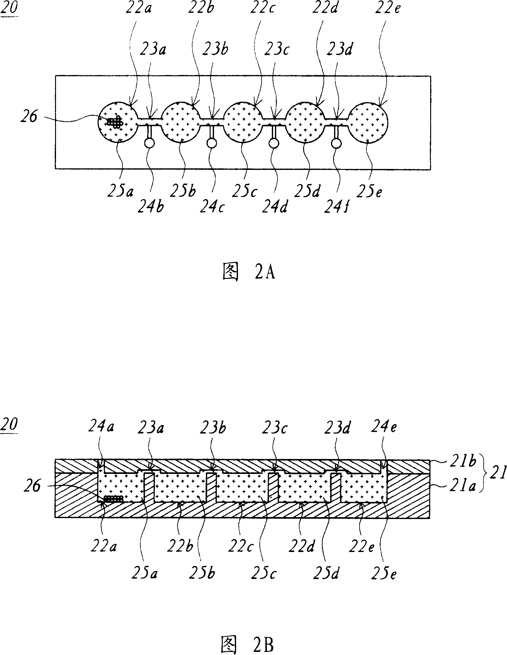
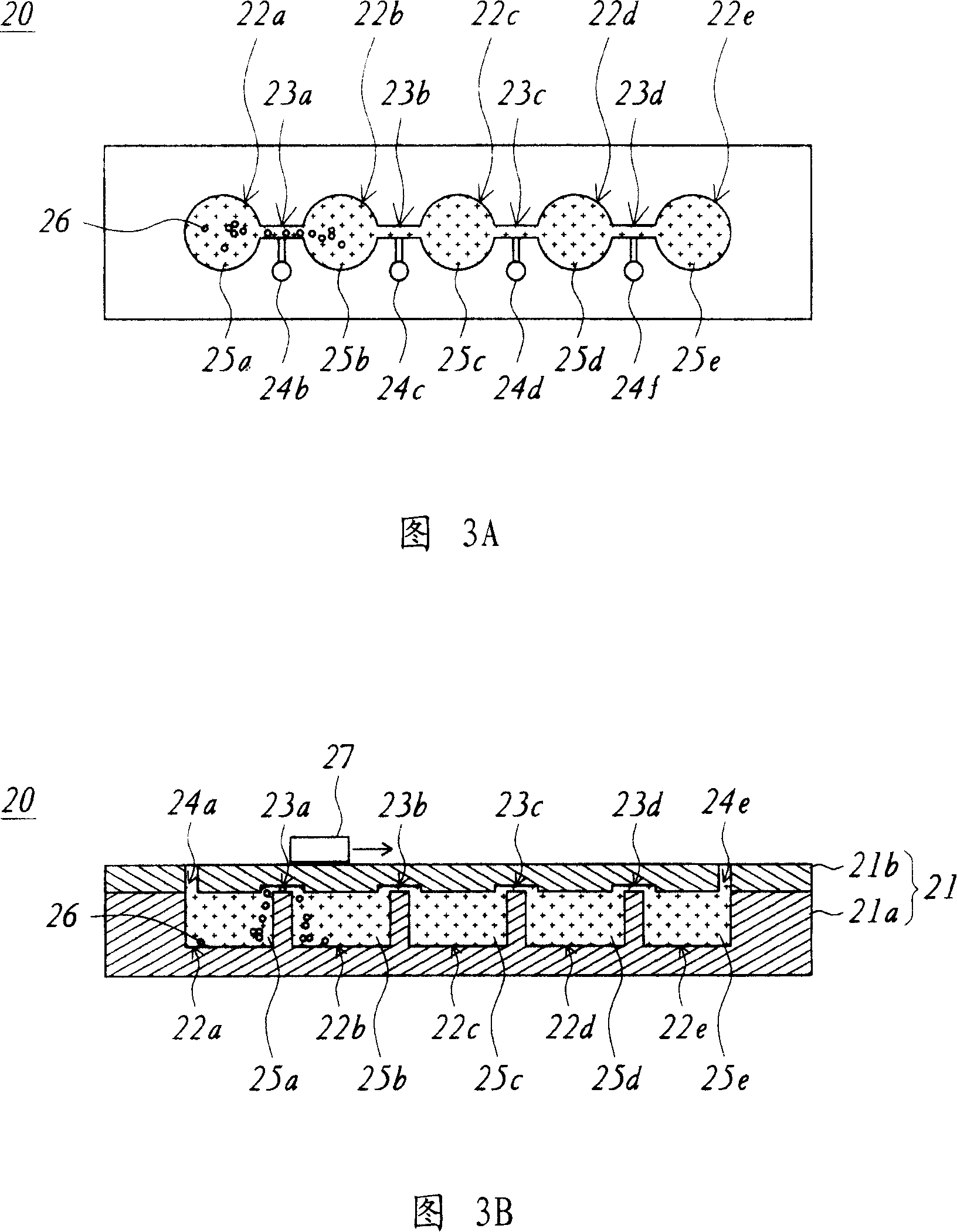
[0046] Please refer to Figures 2A and 2B at the same time, Figure 2A is a top perspective view of the magnetic bead type sample separation device according to Embodiment 1 of the present invention, and Figure 2B is a transverse section of the magnetic bead type sample separation device in Figure 2A picture. The magnetic bead sample separation device 20 includes a main body 21, five reaction tanks 22a-22e, and four microfluidic tubes 23a-23d. The body 21 has six openings 24a to 24f. The reaction tanks 22 a to 22 e are provided in the main body 21 . The reaction tank 22a (such as the first reaction tank) is used to be injected with the mixed solution 25a. The mixed solution 25a contains at least a plurality of magnetic beads 26 and the sample extract, and the sample extract is combined with the magnetic beads 26 . The reaction tank 22b (eg, the second reaction tank) is filled with the washing buffer 25b. The reaction tank 22c is filled with a washing buffer 25c. The reaction...

Embodiment 2

[0056] Please refer to Figures 6A-6C at the same time. Figure 6A is a top perspective view of the magnetic bead type sample separation device according to Embodiment 2 of the present invention, and Figure 6B is a longitudinal section of the magnetic bead type sample separation device in Figure 6A. Fig. 6C is a transverse cross-sectional view of the magnetic bead sample separation device in Fig. 6A. It should be noted that Figure 6B is a cross-sectional view of the rightmost row of reaction tanks and micro-channels in Figure 6A, and Figure 6C is a cross-sectional view of the top row of reaction tanks and micro-channels in Figure 6A. Cutaway diagram. The magnetic bead sample separation device 30 includes a reaction tank array base 40 and a microchannel array top cover 50 . The reaction tank array base 40 includes a base body 41, two reaction tanks 42a and 42b arranged in the same row (such as the first reaction tank), two reaction tanks 43a and 43b arranged in the same row (suc...

Embodiment 3

[0070] Please refer to FIG. 8 , which is a top perspective view of the magnetic bead type specimen separation device according to Embodiment 3 of the present invention. The magnetic bead-type sample separation device 90 includes a reaction tank array base 70 and a microchannel array cover 80. In this embodiment, the reaction tank array base 70 can be expanded from the reaction tank array base 40 in the second embodiment to more than two rows of reaction chambers. Grooves (such as four columns of reaction tanks, each column has five reaction tanks), and the microchannel array top cover 80 in this embodiment can also be expanded to more than two rows of longitudinal microchannel array top covers 50 in the second embodiment. Flow channels (such as four rows of vertical micro-channels, each row has four vertical micro-channels) and more than one row of horizontal micro-channels (such as three rows of horizontal micro-channels, each row has five horizontal micro-channels).

[0071]...


PUM


Abstract

A kind of bead check separation setting, it includes the first reaction groove, the second reaction groove, the third reaction groove, the first miniflow pipe and the second miniflow pope. The first reaction groove has mixture liquid, the mixture liquid includes multiply bead and check extraction, the check extraction combines with the bead. The second reaction groove has cleanout buffer solution to clean the bead. The third reaction groove has separation buffer solution to separate the bead and the cleanout buffer solution. The first miniflow pope is used to connect the first reaction groove and the second reaction groove, and allows the bead to move from the first reaction groove to the second reaction groove. The second miniflow pipe is used to connect the second reaction groove and the third reaction groove, and allows the bead to move from the second reaction groove to the third reaction groove.

Description

【Technical field】 [0001] The present invention relates to a magnetic bead type specimen separation device, and in particular to a magnetic bead type specimen separation device using multiple sequential reaction tanks and dislocation microfluidic network movement. 【Background technique】 [0002] Magnetic bead separation technology has been widely used in immunoassays, especially in the analysis of sample extracts such as protein, deoxyribonucleic acid (DNA) and ribonucleic acid RNA. Among them, there are generally two methods for the operation technology of magnetic bead separation, one is to use manual operation, and the other is to use mechanical automation equipment. [0003] In terms of the manual operation process, please refer to FIG. 1 , which is a schematic flow chart of US Pat. No. 6,187,270 B1 using magnetic beads to separate sample extracts. First, the mixed solution 11 is poured into the test tube 16, the mixed solution 11 contains a plurality of magnetic beads 1...

Claims


Application Information

Patent Timeline
Patent Type & Authority Applications(China)
IPC IPC(8): G01N33/53G01N1/28B03C1/00
Inventor 余东铭
Owner IND TECH RES INST
Why Eureka
Try Eureka