
Touch control input device, touch positioning device and its method

An input device and touch positioning technology, which is applied in the input/output process of data processing, instruments, electrical digital data processing, etc., can solve the problems of difficult production, complicated process, and increased cost, so as to expand the range of positioning objects and save Port resources, easy to produce effects

Inactive Publication Date: 2008-03-26
SUNPLUS TECH CO LTD +1
View PDF0 Cites 17 Cited by
  • Summary
  • Abstract
  • Description
  • Claims
  • Application Information

AI Technical Summary

Problems solved by technology

[0005] Although this existing touch screen technology is relatively convenient for the user's input operation, there are following defects in this existing resistive touch screen: 1) the transparent conductive coating material is ITO indium oxide or nickel-gold coating, because both of them need to be considered Its transparency, and the transparency can only be realized when the thickness of the material reaches a certain standard, so the requirements for the conductive material itself are high, thereby increasing the cost; 2) The method of laying a resistive electric field on the touch panel as a whole is complicated in process and difficult in production Large, and mainly used in high-precision transparent touch applications;
However, this technology still needs to use a transparent touch panel to correspond to the physical object below; at the same time, in order to meet the requirements of precise positioning, the layout of the conductive strip on the panel is required to be fine, and the analog / digital converter also puts forward higher requirements. , otherwise precise positioning cannot be achieved

Method used


Image

  • Touch control input device, touch positioning device and its method
  • Touch control input device, touch positioning device and its method
  • Touch control input device, touch positioning device and its method

Examples


Embodiment Construction

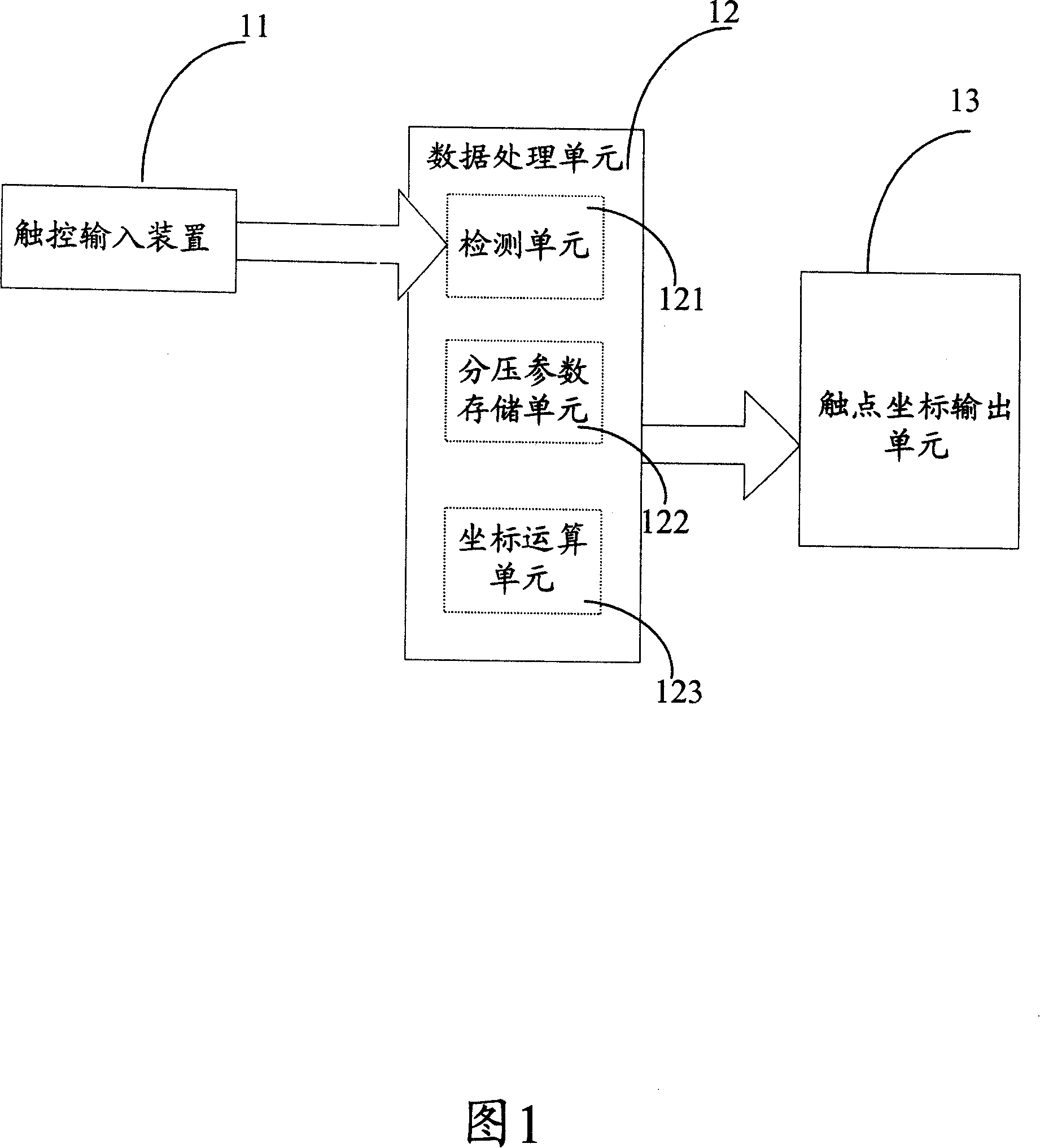
[0026] Referring to FIG. 1 , it is a control block diagram of a touch positioning device according to an embodiment of the present invention, including a touch input device 11 , a data processing unit 12 , and a contact coordinate output unit 13 . in:

[0027] The touch input device 11 is used to receive the user's touch input, and output the X and Y direction voltage division parameters of the touch point when the user touches according to the voltage loaded by the detection device;

[0028] The data processing unit 12 is connected to both ends of the resistance network of the touch input device, and is used to detect the input signal of the touch input device, and calculate and obtain the coordinate data of the corresponding touch point;

[0029] The contact point coordinate output unit 13 is configured to output the coordinate position of the touch location.

[0030] Referring to FIG. 1 , the data processing unit 12 may include: a detection unit 121 , a voltage division pa...


PUM


Abstract

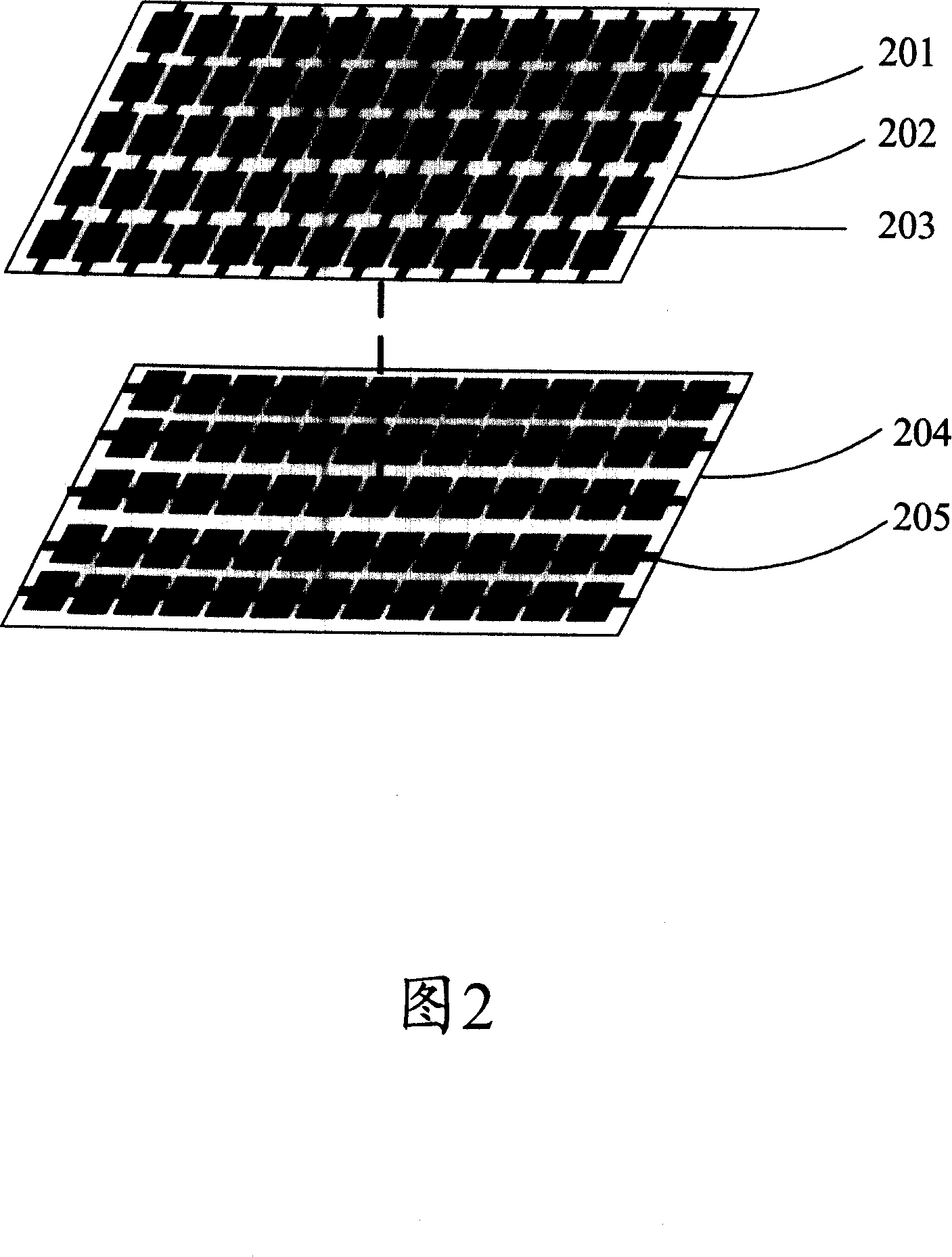
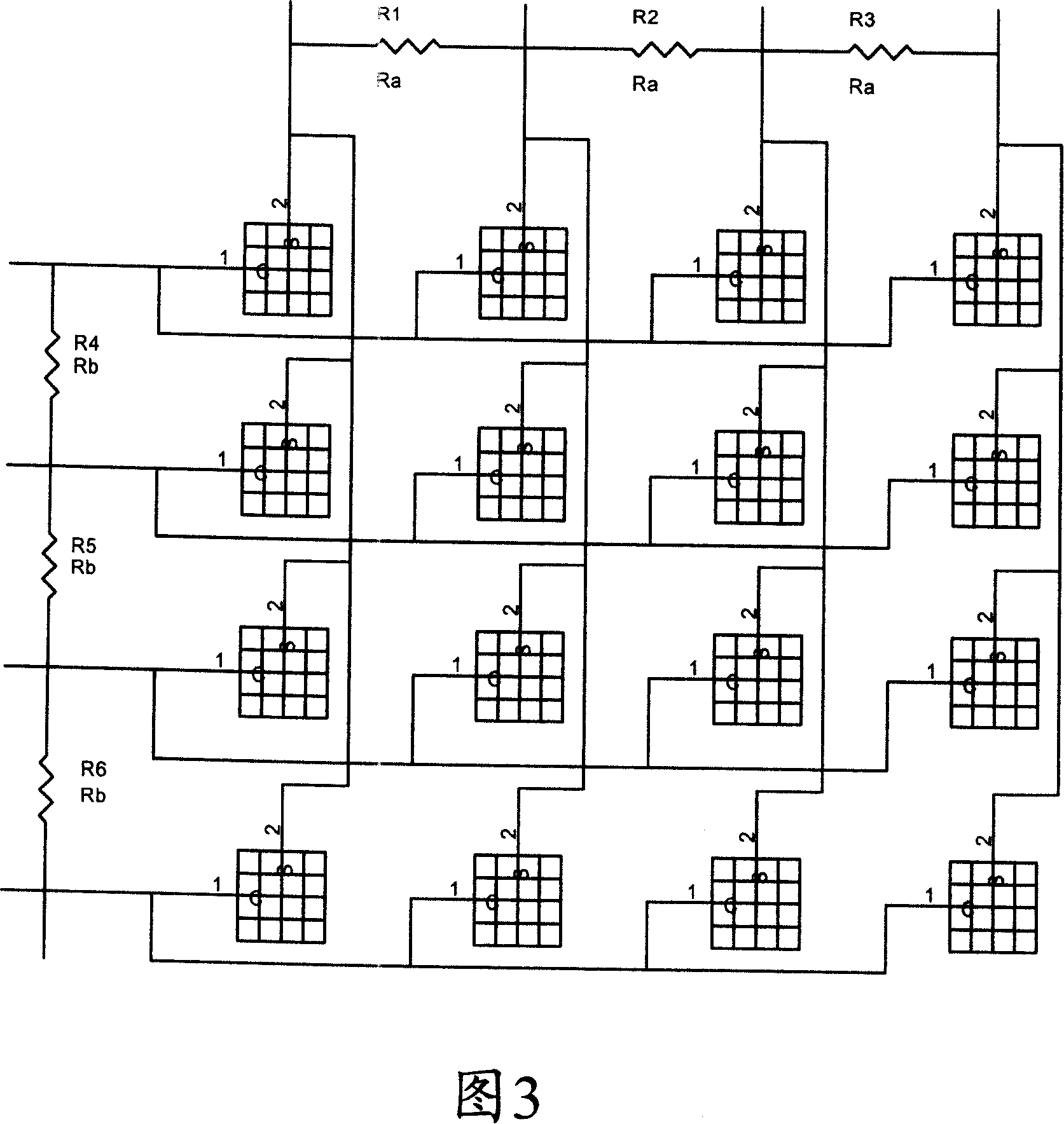
This invention discloses a touch-control input device, as well as the touching positioning device which uses the touch-control input device and its allocation method. This invention includes the first printed circuit level and the second printed circuit level: the first, second printed circuit level includes an insulation material base separately, in one side of this base, has many mutually parallel wires printed horizontally or vertically, many carbon film contact points lay down along each wire in order, then to form the carbon film contact point matrix; a resistance is separately between each neighboring wire bridge in bridge, forms the resistance network with a series connection; to fold opposite direction fixedly the first printing with the second printed circuit level which has wire, the corresponding carbon film contact point does not contact when does not have the pressure, and contacts when meets the pressure, to cause the corresponding horizontal wire and the vertical wire with connection. This localization of this invention is accurate, so saves the port, and the cost is low.

Description

technical field [0001] The present invention relates to an input device, a positioning device and a method thereof, in particular to a touch control input device formed of a conductive carbon film, a touch positioning device using the touch input device and a positioning method thereof. Background technique [0002] Generally speaking, at present, in e-books and other educational electronic products, the input and positioning of book page content mostly adopts the method of button type or electromagnetic induction pen. However, due to the limited number of button layouts for this button-type input, the detection of buttons needs to consume more hardware resources; while the electromagnetic induction pen method is more expensive, and needs to use a pen to indicate and locate, which is not enough for children. direct. [0003] The existing touch screen technology is the most acceptable input method of electronic products for ordinary people after keyboard, mouse, tablet and v...

Claims


Application Information

Patent Timeline
IPC IPC(8): G06F3/045
Inventor 罗立声魏优兵
Owner SUNPLUS TECH CO LTD
Learn More