Amorphous alloy roll-core and its production method

An amorphous alloy, coiled iron core technology, applied in the field of transformer manufacturing, can solve problems such as unfavorable promotion, increase in no-load loss, and decline in core performance, saving amorphous alloy materials, reducing the possibility of failure, and reducing load. The effect of loss

Active Publication Date: 2008-03-26
NEWONDER SPECIAL ELECTRIC
View PDF0 Cites 41 Cited by
  • Summary
  • Abstract
  • Description
  • Claims
  • Application Information

AI Technical Summary

Problems solved by technology

[0009] c. The material of the opening part of the open iron core has to be bent many times, especially the bending of the material after annealing, which will increase the stress of the material, reduce the performance of the iron core, and increase the no-load loss
[0010] d. There are gaps at the junction of the amorphous alloy material at the opening of the open-type iron core, and the joint is not tight enough. The noise is larger than that of the closed-end iron core with the same capacity.
[0011] e. When the amorphous alloy material at the opening is closed, the amorphous alloy material is bent, and the surface of the amorphous alloy material is easy to fall off, resulting in fish scale flakes. These flakes floating in the transformer oil are likely to cause transformer failure and make the transformer decreased security
[0012] f. Because the amorphous alloy material is too thin, the iron core made of it has poor rigidity and cannot bear the weight of the wire package. Supports must be added to bear the weight of the iron core, which increases the difficulty of body assembly
[0013] g. Amorphous alloy materials are relatively expensive, and the source of materials is single, which is not conducive to mass promotion

Method used


Image

  • Amorphous alloy roll-core and its production method
  • Amorphous alloy roll-core and its production method
  • Amorphous alloy roll-core and its production method

Examples


Embodiment 1

[0055] 1. Embodiment 1: Single-phase open coil core

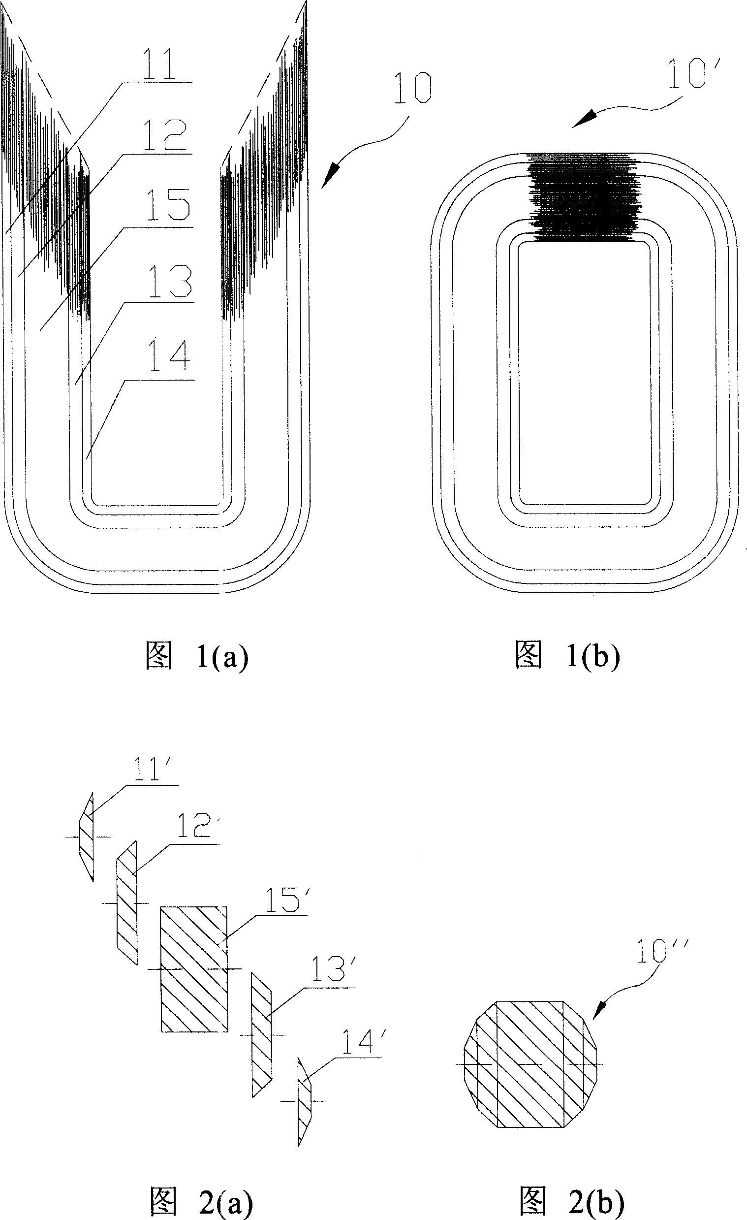
[0056] As shown in FIG. 1( a ), the amorphous alloy single-phase open coiled iron core 10 according to the present invention, as shown in FIG. 1( b ), forms a closed coiled iron core 10 ′ after the opening part is closed.

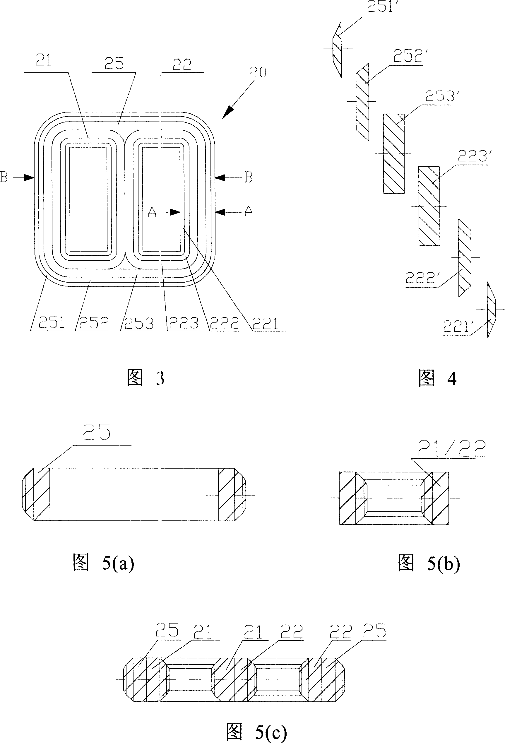
[0057] The iron core is composed of five U-shaped single frames 11, 12, 13, 14 and 15 with different cross-sectional shapes. Wherein the U-shaped single frame 15 with the largest cross-sectional area is the main frame, and the main frame is made of amorphous alloy material, and all the other single frames 11, 12, 13, 14 are made of silicon steel strip material. The cross-sectional shape of each single frame is shown in Figure 2(a). The cross-section 15' of the main frame and the cross-sections 11', 12', 13', and 14' of the other single frames are combined to form a U-shaped single-phase open coil core. The cross-section 10 ", the shape is shown in Fig. 2(b).

[0058] When the U-shaped single frames are...

Embodiment 3

[0073] Embodiment 3: Three-phase three-column three-dimensional closed coil core

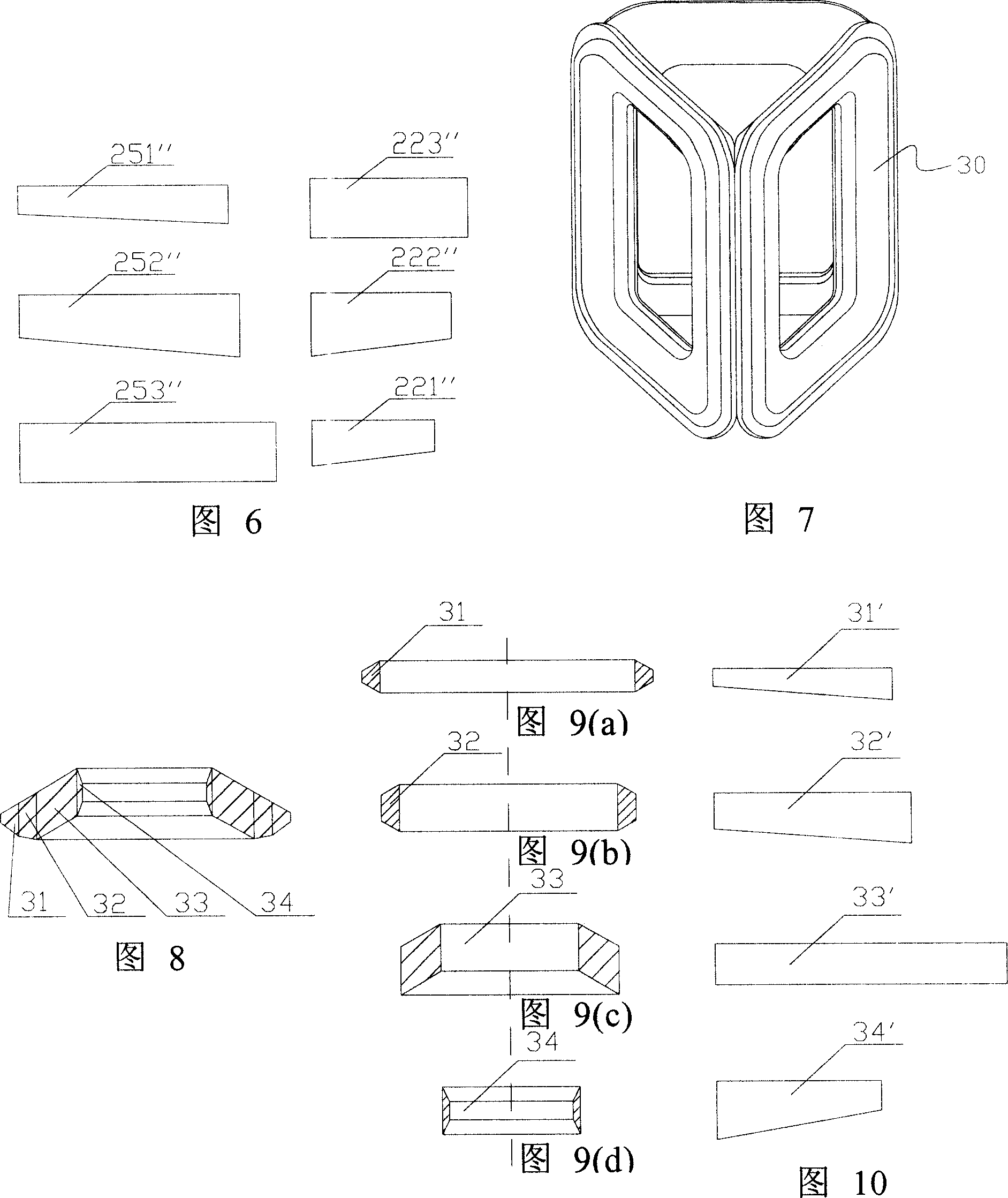
[0074] As shown in Fig. 7, the three-phase three-column three-dimensional closed coil core of the present invention is composed of three closed unit frames 30 with the same or substantially the same shape, and the cross-section of each unit frame 30 As shown in Figure 8, each unit frame is composed of four single frames 31, 32, 33, 34, the single frame 33 with the largest cross-sectional area among the four single frames is the main frame, and the main frame 33 is composed of non- The crystal alloy material is formed after winding and annealing, and the other single frames 31, 32, 34 are formed by winding and annealing silicon steel strips. The cross-sectional shape of each single frame is as shown in Figure 9, and the shape of each material strip forming each single frame is as shown in Figure 10. The strips are respectively 31', 32', 34'.

[0075] Manufacturing method of the present inventio...


PUM


Abstract

This invention relates to a non-crystal alloy rolled iron-core and its manufacturing method, in which, the iron-core is formed by several single frames winded in different sections and the section shape of the butt-joint iron-core is in a pre-designed Quasi-circular, quasi-polygon or a complex shape made of non-crystal alloy material or non-crystal alloy and silicon steel ribbon, in which, the one with the largest section is taken as the master frame rolled continuously with the straight non-crystal alloy ribbon and other single frames are formed by rolling different shapes of silicon steel ribbons, besides, the butt-joint core can be either close one or an open one, can be either single phase iron-core, three phase three posts planar core or a three phase five posts planar core or a three phase solid core.

Description

technical field [0001] The invention relates to a transformer manufacturing technology, in particular to an amorphous alloy wound iron core and a manufacturing method thereof. Background technique [0002] At present, the materials for making transformer iron core mainly include silicon steel strip and amorphous alloy. Compared with silicon steel strip, amorphous alloy is a more energy-saving material for manufacturing transformer iron core. [0003] Amorphous alloy is produced by rapid rapid cooling and solidification, and its physical state is that the metal atoms are arranged in a disordered amorphous manner, which is more conducive to magnetization and demagnetization. This material is used in the transformer core, and the transformer magnetization process is very easy, thereby greatly reducing the no-load loss of the transformer. From the point of view of the reduction of the no-load loss of the transformer, the amorphous alloy strip is incomparable to all the current ...

Claims


Application Information

Patent Timeline
Patent Type & Authority Applications(China)
IPC IPC(8): H01F3/04H01F27/25H01F41/02
Inventor 张明德
Owner NEWONDER SPECIAL ELECTRIC
Why Eureka
Try Eureka