Wave division multiplexing optical transmission system

A transmission system and wavelength division multiplexing technology, applied in the field of optical transmission technology, can solve problems such as waste of line fiber resources, and achieve the effects of reducing professional quality requirements, improving utilization, and avoiding waste.

Inactive Publication Date: 2008-03-26
ZTE CORP
View PDF0 Cites 5 Cited by
  • Summary
  • Abstract
  • Description
  • Claims
  • Application Information

AI Technical Summary

Problems solved by technology

[0009] The technical problem solved by the present invention is to provide a wavelength division multiplexing optical transmission system, which solves the problem of resource waste in the line fiber protection of conventional wavelength division multiplexing optical transmission systems, and improves the utilization rate of line fibers

Method used


Image

  • Wave division multiplexing optical transmission system
  • Wave division multiplexing optical transmission system
  • Wave division multiplexing optical transmission system

Examples


Embodiment Construction

[0027] The preferred embodiments of the present invention will be described in detail below with reference to the accompanying drawings.

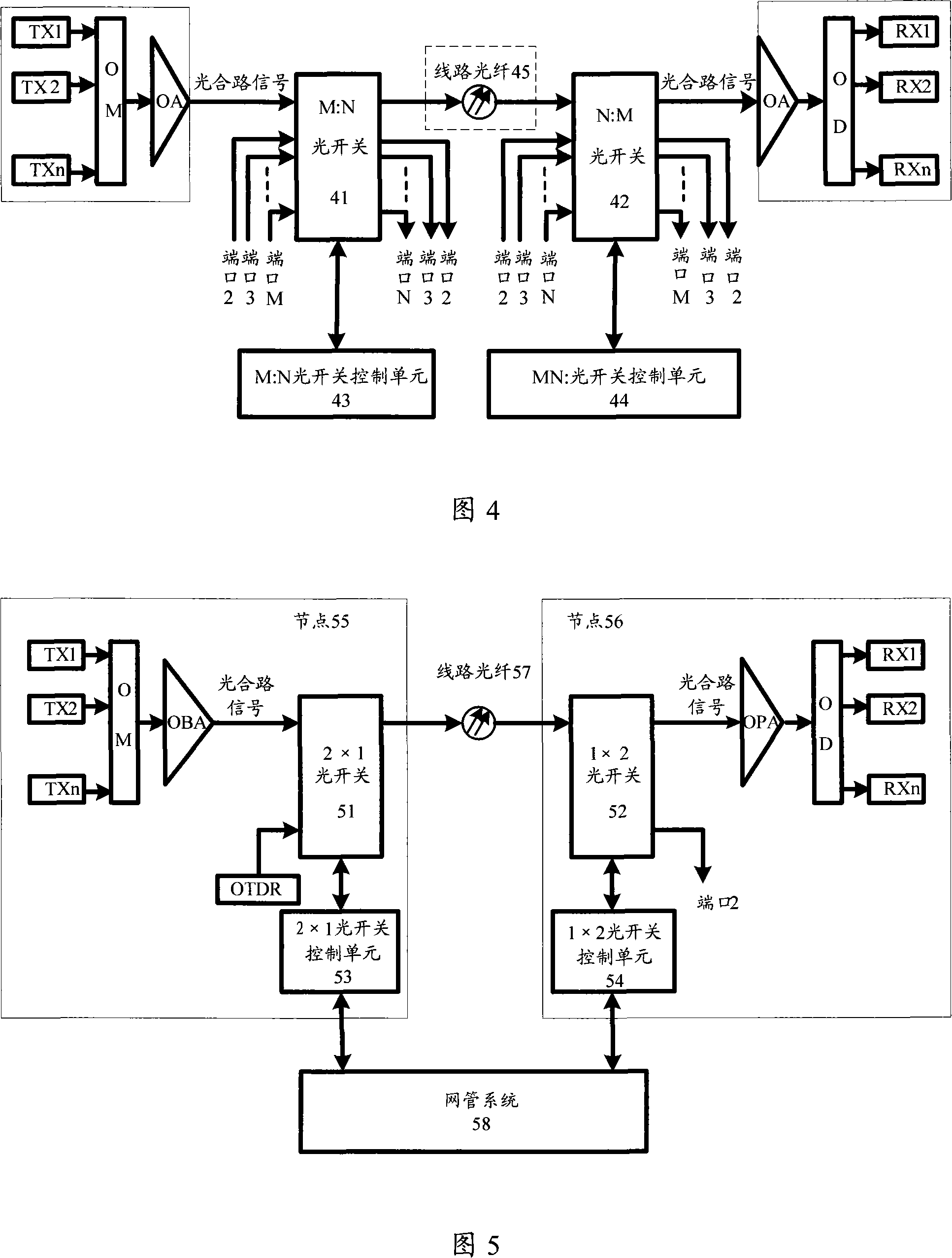
[0028] Referring to FIG. 4 , it is a structural block diagram of the wavelength division multiplexing optical transmission system of the present invention. The wavelength division multiplexing optical transmission system consists of transmitters TM1~TMn, optical multiplexers OM, optical amplifiers OA, line fibers 45, optical demultiplexers OD, and optical receivers RM1~RMn. On the basis of the system, an M:N optical switch 41, an M:N optical switch control unit 43, an N:M optical switch 42, and an N:M optical switch control unit 44 are added on both sides of the line optical fiber 45 to form a new type of Wavelength division multiplexing optical transmission system. Where M and N are positive integers, generally M≥N.

[0029] The input of the optical combination signal is connected to the input port 1 of the M:N optical switch 41, and the...


PUM


Abstract

This invention discloses a WDM optical transmission system, in which, the WD devices are connected by circuit fibers and both ends of the circuit fiber are set with a first optical switch and a second optical switch used in switching connection of thefiber and the WD device, each of the two switches is set with at least a pair of input and output ports, the first switch is conneted with its control unit used in controlling set of optical paths of the input and output ports of the first optical switch, sid second optical switch is connected with the its control unit, which is used in controlling collocation of the input and output ports of the second optical switch.

Description

technical field [0001] The invention relates to an optical transmission technology in the communication field, in particular to a wavelength division multiplexing optical transmission system. Background technique [0002] Figure 1 is a schematic diagram of a conventional wavelength division multiplexing (WDM) optical transmission system, which consists of an optical transmitter TM, an optical multiplexer OM, an optical amplifier OA, an optical demultiplexer OD, an optical receiver RM, and a line fiber . The optical signal emitted by the optical transmitter TM is combined by the optical multiplexer OM, amplified by the optical amplifier OA, and then transmitted in the line fiber, and then amplified by the optical amplifier OA after a certain distance, and the optical signal transmitted through the line fiber reaches the receiving end When it is first amplified by the optical amplifier OA, and then demultiplexed by the optical demultiplexer OD, it is received by the optical r...

Claims


Application Information

Patent Timeline
Patent Type & Authority Applications(China)
IPC IPC(8): H04B10/08H04B10/12H04J14/02H04B10/25
Inventor 张红宇夏焱李红军苏婕
Owner ZTE CORP
Why Eureka
Try Eureka