DNA on-line separating microcurrent control chip and analytical method thereof

A microfluidic chip and analysis method technology, applied in the field of DNA separation, can solve the problems affecting the actual application value, complex equipment interface, large dead volume, etc., and achieve the effect of improving detection sensitivity, wide practical range, and high sensitivity

Inactive Publication Date: 2008-04-02
DALIAN INST OF CHEM PHYSICS CHINESE ACAD OF SCI
View PDF0 Cites 7 Cited by
  • Summary
  • Abstract
  • Description
  • Claims
  • Application Information

AI Technical Summary

Problems solved by technology

Because the isotachophoretic preconcentration-separation combination method based on the traditional capillary electrophoresis platform requires very complex equipment interfaces, and at the same time causes a large dead volume, which affects its practical application value, and the use of the microfluidic chip platform can easily achieve this.

Method used


Image

  • DNA on-line separating microcurrent control chip and analytical method thereof
  • DNA on-line separating microcurrent control chip and analytical method thereof
  • DNA on-line separating microcurrent control chip and analytical method thereof

Examples


Embodiment 1

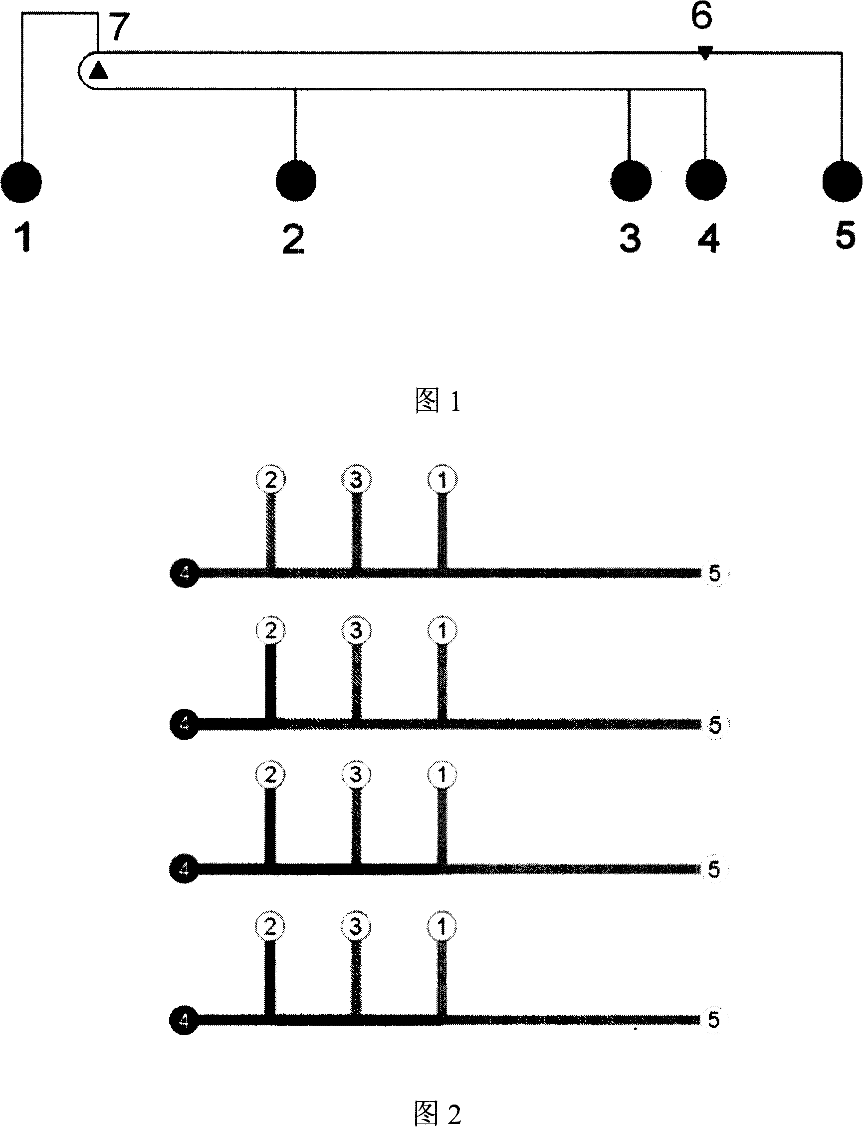
[0051] The integrated microfluidic chip (see Figure 1) is composed of a leading buffer pool 1, a sample pool 3, a buffer waste pool 5, and a separation detection point 6 set close to the inside of the buffer waste pool 5, and outside the sample pool 3 A trailing buffer pool 4 is set; a leading buffer 1 is set in a sample pool 3 and a buffer waste pool 5; a pre-concentration detection point 7 is set at the intersection of the extension channel and the separation channel of the leading buffer pool 1 .

[0052] A sample waste liquid pool 2 is provided between the trailing buffer pool 4 and the leading buffer pool 1 .

[0053] The effective sample area between the sample waste pool 2 and the sample pool 3 is 20 cm.

[0054] When the sample waste liquid pool 2 is between the sample pool 3 and the leading buffer 1, the effective area between the leading buffer 1 and the sample waste liquid pool 2 is 15 cm;

[0055] The liquid storage pools are connected with automatic motors, and a...

Embodiment 2

[0066] The integrated microfluidic chip (see Figure 1) is composed of a leading buffer pool 1, a sample pool 3, a buffer waste pool 5, and a separation detection point 6 set close to the inside of the buffer waste pool 5, and outside the sample pool 3 A trailing buffer pool 4 is set; the leading buffer 1 is set between the sample pool 3 and the buffer waste pool 5; a pre-concentration detection point 7 is set at the intersection of the extension channel and the separation channel of the leading buffer pool 1 .

[0067] A sample waste liquid pool 2 is provided between the trailing buffer pool 4 and the leading buffer pool 1 .

[0068] The effective sample area between the sample waste pool 2 and the sample pool 3 is 2.2 cm.

[0069] When the sample pool 3 is between the sample waste pool 2 and the leading buffer 1, the effective area between the leading buffer 1 and the sample pool 3 is 3 cm.

[0070] When the sample pool 3 is between the sample waste pool 2 and the leading b...

Embodiment 3

[0075] The integrated microfluidic chip (see Figure 1) is composed of a leading buffer pool 1, a sample pool 3, a buffer waste pool 5, and a separation detection point 6 set close to the inside of the buffer waste pool 5, and outside the sample pool 3 A trailing buffer pool 4 is set; a leading buffer 1 is set in a sample pool 3 and a buffer waste pool 3 ; a pre-concentration detection point 3 is set at the intersection of the extension channel and the separation channel of the leading buffer pool 3 .

[0076] A sample waste liquid pool 2 is provided between the trailing buffer pool 4 and the leading buffer pool 1 .

[0077] The effective sample area between the sample waste pool 2 and the sample pool 3 is 10 cm.

[0078] When the sample waste liquid pool 2 is between the sample pool 3 and the leading buffer 1, the effective area between the leading buffer 1 and the sample waste liquid pool 2 is 7 cm;

[0079] The microfluidic chip used was designed by the laboratory itself. I...


PUM


Abstract

The present invention relates to a DNA separation technique, in particular to a micro-fluidic chip for online DNA pre-concentration and separation. The chip consists of a leading buffer pool, a sample pool, a sample waste liquid pool, a buffer waste liquid pool, a terminating buffer pool and channels between the pools, wherein, the terminating buffer pool is arranged at the outer side of the sample pool, and the leading buffer pool is arranged between the sample pool and the buffer waste liquid pool. A separation detection point is arranged near the inside of the buffer waste liquid pool, and a pre-concentration detection point is arranged at the crossing point of an extending channel and a separation channel of the leading buffer pool. The present invention combines online electrophoresis pre-concentration and electrophoresis separation after concentration of DNA samples into the micro-fluidic chip which is of flexible design, simple processing, convenient operation, high sensitivity and extensive application.

Description

technical field [0001] The invention relates to a DNA separation technology, in particular to a microfluidic chip and an analysis method for realizing online DNA separation on a microfluidic chip platform by adopting online electrophoresis pre-concentration and post-concentration electrophoresis separation methods. Background technique [0002] The separation and detection of DNA is an important technical means involved in genetic research. The detected DNA can be amplified or non-amplified samples. For non-amplified samples, a large number of tissues or cells are often required due to the limited copies; for amplified samples, since the concentration of DNA in actual biological samples is generally low, even after PCR amplification, it is not necessary to Sufficient detection sensitivity cannot be guaranteed, and the solution to this problem is to increase the number of polymerase chain reactions at the cost of more reagents and time consumption. For traditional chip elec...

Claims


Application Information

Patent Timeline
IPC IPC(8): C12N15/10C12Q1/68
Inventor 林炳承刘大渔黄淮青
Owner DALIAN INST OF CHEM PHYSICS CHINESE ACAD OF SCI
Why Eureka
Try Eureka