

Routing device, routing method and transmission switching network
A switching network and routing technology, applied in the field of computer networks and routers, can solve the problems of difficult IP network and optical network, complex maintenance of Internet backbone router nodes, and difficulty in further increasing the capacity of backbone routers, so as to simplify networking and maintenance, improve Effects on processing capacity and performance
- Summary
- Abstract
- Description
- Claims
- Application Information
AI Technical Summary
Problems solved by technology
Method used
Image

Examples
Embodiment 1
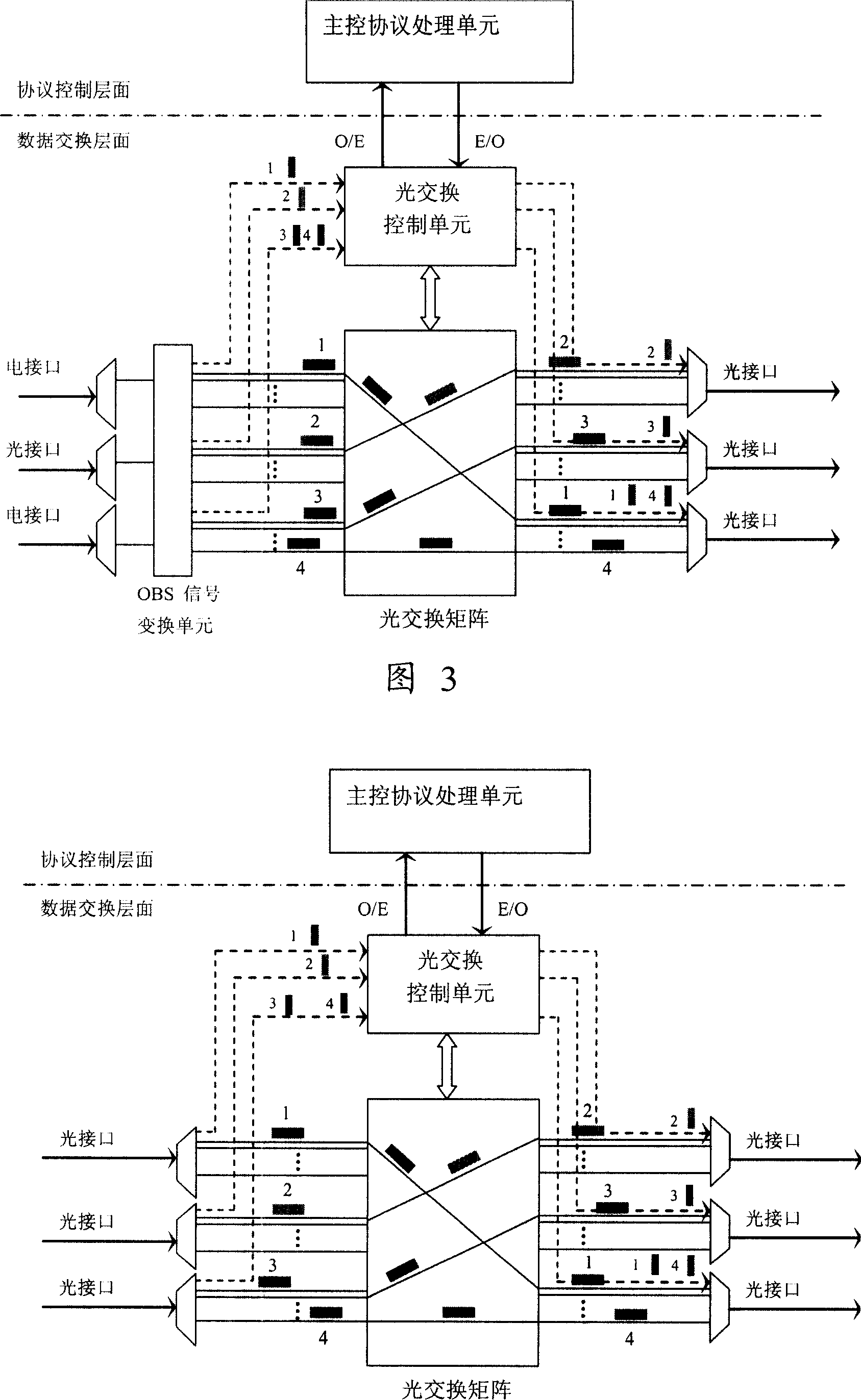
[0121] The idea of this embodiment is that the optical switching technology used here is an electronically controlled optical switching technology that is oriented to the characteristics of IP services and uses optical burst packets (multiple IP packets are aggregated according to a certain mechanism) as the switching unit.
[0122] Among them, "burst" can be regarded as an ultra-long data packet composed of some smaller data packets with the same egress edge node address and / or the same QoS requirements. These data packets can come from IP packets in the traditional IP network. OBS (Optical Burst Switch, optical burst switching) signal burst is the basic switching unit in the optical burst switching network, which consists of a control packet (BCP, Burst Control Packet, which acts as a packet header in packet switching) and a burst The data BP (Burst Packet payload) consists of two parts. Burst data and control packets are separated on the physical channel, and each control...
Embodiment 2
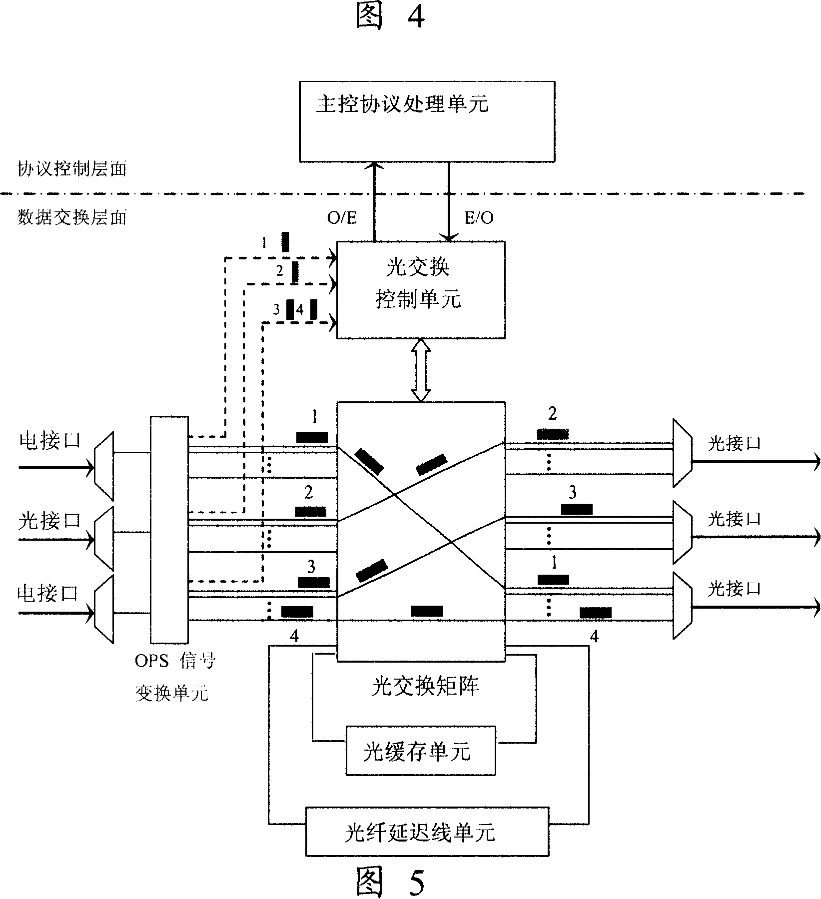
[0132] The idea of this embodiment is that the optical switching technology used here is a packet-oriented optical switching technology, that is, every time an IP packet is received, the data is converted into an OPS (Optical Packet Switching) signal. The OPS signal consists of two parts, a control packet and a payload, and each control packet corresponds to a payload.
[0133] As shown in FIG. 5, the backbone network router in Embodiment 2 of the present invention processes the equipment architecture diagram of electrical and optical signal routing. The numbers 1, 2, 3, and 4 in the figure are only used to mark the routing direction of data packets. The electrical interface inputs or outputs electrical signals, the optical interface inputs or outputs optical signals, and the OPS signal conversion unit completes the conversion of electrical signals and optical signals in the format defined by the backbone router, as well as the conversion of other types of optical signals and...
PUM
 Abstract
Description
Claims
Application Information