
Remanent service life prediction method of steam turbine high-temperature component

A high-temperature component and life prediction technology, which is applied in the fields of power engineering and steam turbines, can solve the problems of inability to deal with the remaining life prediction, and does not consider the factors of creep fracture and crack, so as to achieve the effect of improving accuracy and reliability and reducing workload

Inactive Publication Date: 2008-04-16
EAST CHINA UNIV OF SCI & TECH
View PDF3 Cites 59 Cited by
  • Summary
  • Abstract
  • Description
  • Claims
  • Application Information

AI Technical Summary

Problems solved by technology

However, these methods do not consider creep fracture and crack factors, so they cannot deal with the remaining life prediction problem of defects found in engineering detection.

Method used

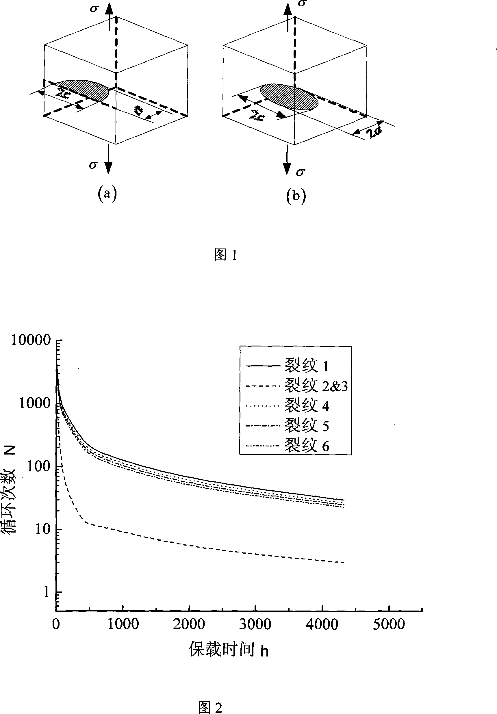

Image

  • Remanent service life prediction method of steam turbine high-temperature component
  • Remanent service life prediction method of steam turbine high-temperature component
  • Remanent service life prediction method of steam turbine high-temperature component

Examples


Embodiment 1

[0066] An in-service medium and high pressure rotor in a power plant is made of CrMoV steel. During routine inspection, some internal defects were found. Due to the limitation of production and manufacturing time of the rotor, the equipment needs to continue running for a period of time before it can be overhauled.

[0067] In order to ensure the reliability of the rotor during the period of time thereafter, the remaining life prediction method of the present invention is used to predict the remaining life of the rotor and give a safety judgment.

[0068] Determining Material Properties

[0069] Using the CT sample of CrMoV steel, using the electronic creep fatigue testing machine, using the direct current potential method, the material properties of CrMoV steel are obtained, as follows:

[0070] Fatigue crack growth constant C at room temperature 0 =1.43×10 -8 , the crack growth exponent n 0 = 2.7;

[0071] At the working temperature (522°C), the creep crack growth coef...

Embodiment 2

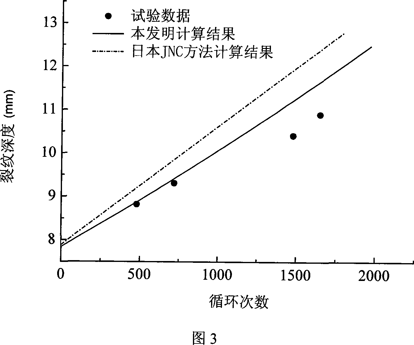
[0096] According to the test data of foreign researchers, the test results, the life predicted by the Japanese JNC method and the life predicted by the method of the present invention are compared.

[0097] The sample material is a 361L stainless steel plate with a thickness of 24.5mm and a half oval surface crack, the crack length is 2c=87.2mm, the depth is a=7.9mm, the test temperature is 650°C, and the fatigue crack growth constant is C 0 =6.2×10 -8 , the crack growth exponent n 0 =2.46; Creep crack growth coefficient B=0.0071, expansion index q=0.73, holding time is 1h, maximum stress σ max =141.5MPa, stress amplitude Δσ=283MPa.

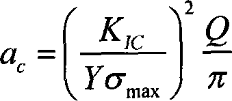
[0098] Since the size and shape of the crack and the stress distribution of the sample have been determined, the calculation of the number of cycles can be performed directly. In the calculation, the crack increment is taken as Δa=0.01mm, and the critical crack size is taken as a c = 12.7 mm. Comparing the calculation results with the test d...


PUM

PropertyMeasurementUnit
Stressaaaaaaaaaa
Crack lengthaaaaaaaaaa
Maximum stressaaaaaaaaaa

Abstract

The invention discloses a method for predicting the remaining lifetime of a high-temperature part of a steam turbine after defects are found, including the following steps of: obtaining the material property of the material of the high-temperature part of the steam turbine at different temperatures; performing nondestructive flaw detection on the high-temperature part of the steam turbine; regularizing cracks obtained by nondestructive flaw detection as elliptic type cracks; analyzing and evaluating the interference and communication between cracks; analyzing the stress of the high-temperature part; predicting the remaining lifetime of the high-temperature part of the steam turbine. The invention has the advantages of taking reasonably the coupling effect of fatigue and creep deformation on the lifetime into consideration, realizing the judgment of cracks interference and combination, improving the calculation accuracy of the remaining lifetime of the high-temperature part of the steam turbine; therefore, the invention can be used to support the analysis of safety performance of defects and the prolonging of the service life of the high-temperature part in the manufacturing process and to guide the reasonable making of repair schedule.

Description

technical field [0001] The invention belongs to the technical fields of power engineering and steam turbine, and in particular relates to a method for predicting the remaining life of high-temperature components of a steam turbine, in particular to a method for testing and evaluating the life of a high-temperature component of a steam turbine after a defect is found, which can be applied to the life management and control of components of a steam turbine generator set. Background technique [0002] Statistics show that at present, 80% of the electricity in our country is undertaken by thermal power generating units, and in thermal generating units, the most important equipment is the steam turbine. Due to the harsh working environment of some key components of steam turbines, not only long-term operation at high temperature, but also often subjected to severe alternating stress, defects or cracks in these components are unavoidable. Knowledge of fracture mechanics and engine...

Claims


Application Information

Patent Timeline
IPC IPC(8): G01N35/00G01M15/00G06F19/00G06F17/13
Inventor 轩福贞司俊刘晓涂善东
Owner EAST CHINA UNIV OF SCI & TECH
Learn More