Gate driver, electro-optical device, electronic instrument, and drive method

A gate driver, optoelectronic device technology, applied in the fields of instrumentation, optics, nonlinear optics, etc., can solve the problems of increased charge and discharge charge, weakened effect of low power consumption, power consumption dependence, etc., to achieve low power consumption Optimizing and reducing power consumption

Inactive Publication Date: 2008-04-16
SEIKO EPSON CORP
View PDF1 Cites 4 Cited by
  • Summary
  • Abstract
  • Description
  • Claims
  • Application Information

AI Technical Summary

Problems solved by technology

[0008] However, the technique disclosed in Patent Document 1 has a problem that the reduction effect of power consumption depends on the voltage given on the source line.
Therefore, there are cases where the reduction effect of the amount of electric charge that charges and discharges the counter electrode whose polarity is reversed is less than ideal
In addition, in the technique disclosed in Patent Document 1, there is a problem in that the two electrodes interposing the liquid crystal are short-circuited depending on the relationship between the voltage given on the source line and the polari

Method used


Image

  • Gate driver, electro-optical device, electronic instrument, and drive method
  • Gate driver, electro-optical device, electronic instrument, and drive method
  • Gate driver, electro-optical device, electronic instrument, and drive method

Examples


Embodiment Construction

[0045] Preferred embodiments of the present invention will be described in detail with reference to the following drawings. In addition, the Examples described below do not unduly limit the content of the present invention described in the claims. Not all structures described below are necessarily essential components of the present invention.

[0046] 1. Liquid crystal device

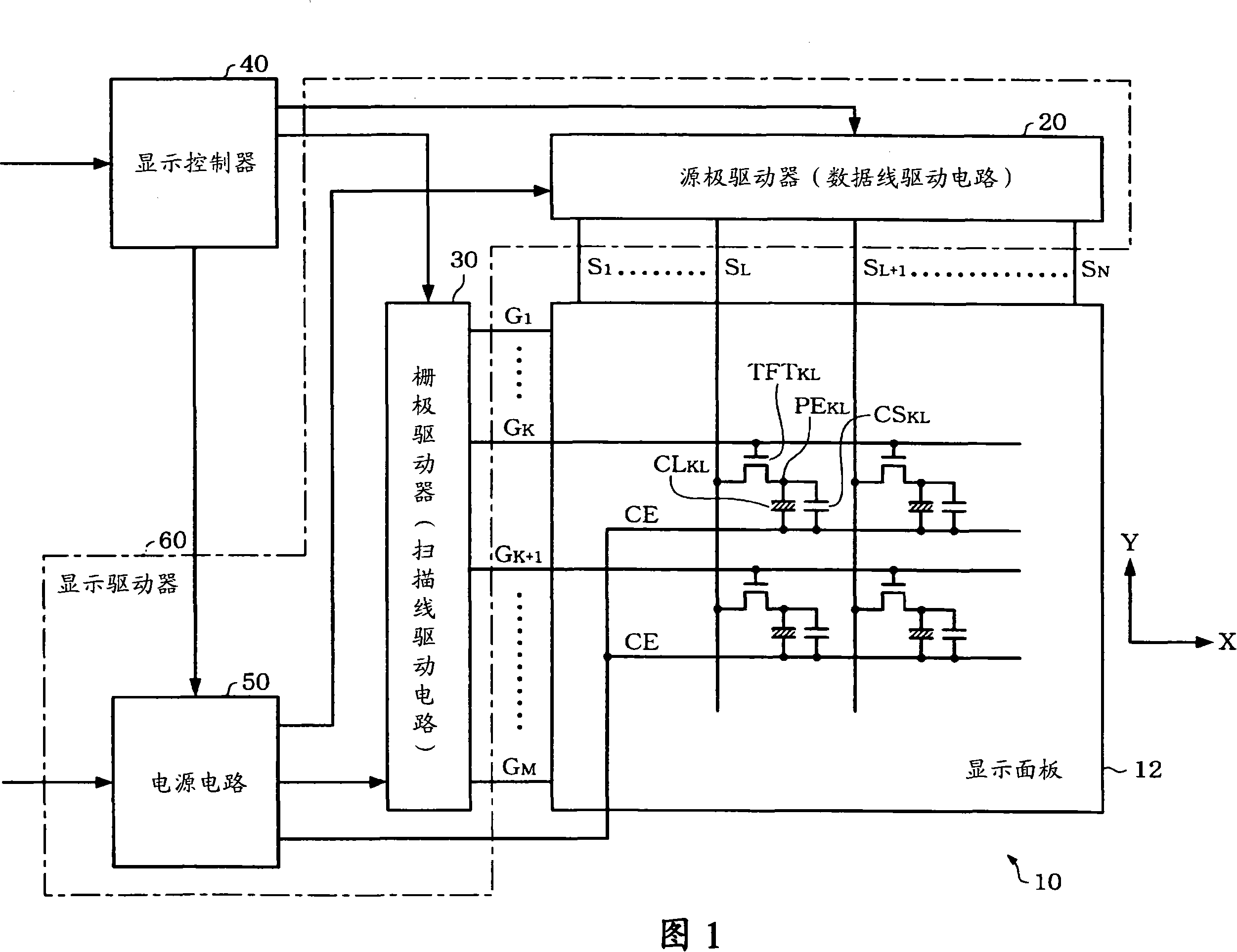
[0047] FIG. 1 is an example of a block diagram of a liquid crystal device of this embodiment.

[0048] A liquid crystal device 10 (a liquid crystal display device. A display device in a broad sense) includes a display panel 12 (a liquid crystal panel in a narrow sense, an LCD (Liquid Crystal Display) panel), a source driver 20 (a data line drive circuit in a broad sense), a gate A driver 30 (scanning line driving circuit in a broad sense), a display controller 40 , and a power supply circuit 50 . In addition, the liquid crystal device 10 does not necessarily include all of these circuit blocks, and ...


PUM


Abstract

A gate driver includes a first gate output circuit which outputs a select signal for selecting the first gate line, a second gate output circuit which outputs a select signal for selecting the second gate line in a select period subsequent to the select period of the first gate line, and a transistor as a first gate line short-circuiting circuit provided between outputs of the first and second gate output circuits. The transistor short-circuits the outputs of the first and second gate output circuits in a period between the select period of the first gate line and the select period of the second gate line.

Description

technical field [0001] The invention relates to a gate driver, an optoelectronic device, an electronic device, a driving method and the like. Background technique [0002] In recent years, as a liquid crystal display (Liquid Crystal Display: LCD) panel (a display panel in a broad sense; an optoelectronic device in a broader sense) mounted on electronic equipment such as a mobile phone, there are known simple matrix LCD panels and the use of An active-matrix LCD panel using switching elements such as thin film transistors (Thin Film Transistor: hereinafter referred to as TFT). [0003] The simple matrix method is easier to achieve lower power consumption than the active matrix method, but it is difficult to realize multi-color and moving image display. On the other hand, the active matrix method is suitable for multi-color and moving image display, but it is difficult to achieve low power consumption. [0004] A simple matrix type LCD panel or an active matrix type LCD pane...

Claims


Application Information

Patent Timeline
IPC IPC(8): G02F1/1362G09G3/36
Inventor 西村元章
Owner SEIKO EPSON CORP
Why Eureka
Try Eureka