Wheel brake

A wheel brake and brake technology, applied in the direction of brake type, brake components, axial brake, etc., can solve the problems of adjustment device failure, can not completely avoid the influence of automobile electric energy and signal system, etc., to achieve the effect of compact structure

Active Publication Date: 2008-04-16
BPW BERGISCHE ACHSEN KOMMANDITGES
View PDF4 Cites 12 Cited by
  • Summary
  • Abstract
  • Description
  • Claims
  • Application Information

AI Technical Summary

Problems solved by technology

Therefore, the failure of the electric energy and signal system of the car itself also causes the failure of the adjustment device.
[0005] If, as proposed, for example, in DE 10342281 A1, the adjusting device of the disc brake is operated pneumatically connected to the vehicle's compressed air source, then the influence of the vehicle's own electrical energy and signal system cannot be completely avoided

Method used


Image

  • Wheel brake
  • Wheel brake
  • Wheel brake

Examples


Embodiment Construction

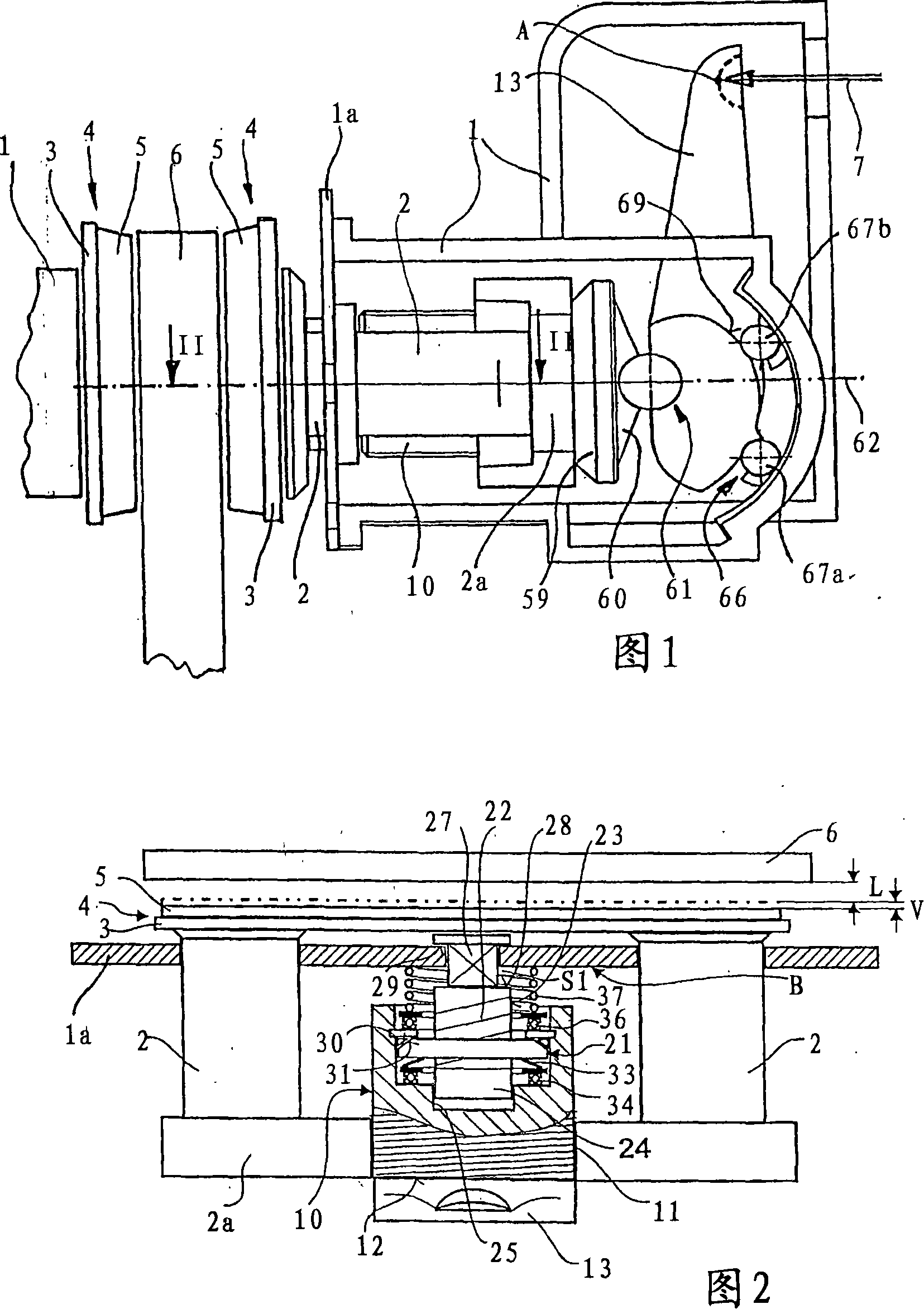
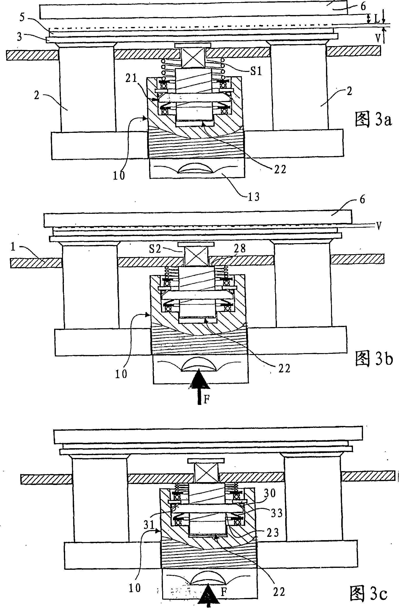
[0043] FIG. 1 shows a simplified illustration of part of a brake housing 1 of a motor vehicle disc brake, in particular of the floating caliper design. The two pressure plungers 2 are connected to each other within the brake housing 1 via a yoke 2 a extending transversely to the pressure plungers. Thus, as can be seen in particular from FIG. 2 , the two pressure plungers 2 form a double plunger which is supported outside the brake housing 1 on the rear side of the cover plate 3 of the brake lining 4 . 1 and 2 also show a brake lining 5 in addition to the brake lining 4 and also a brake disk 6 of the disk brake.

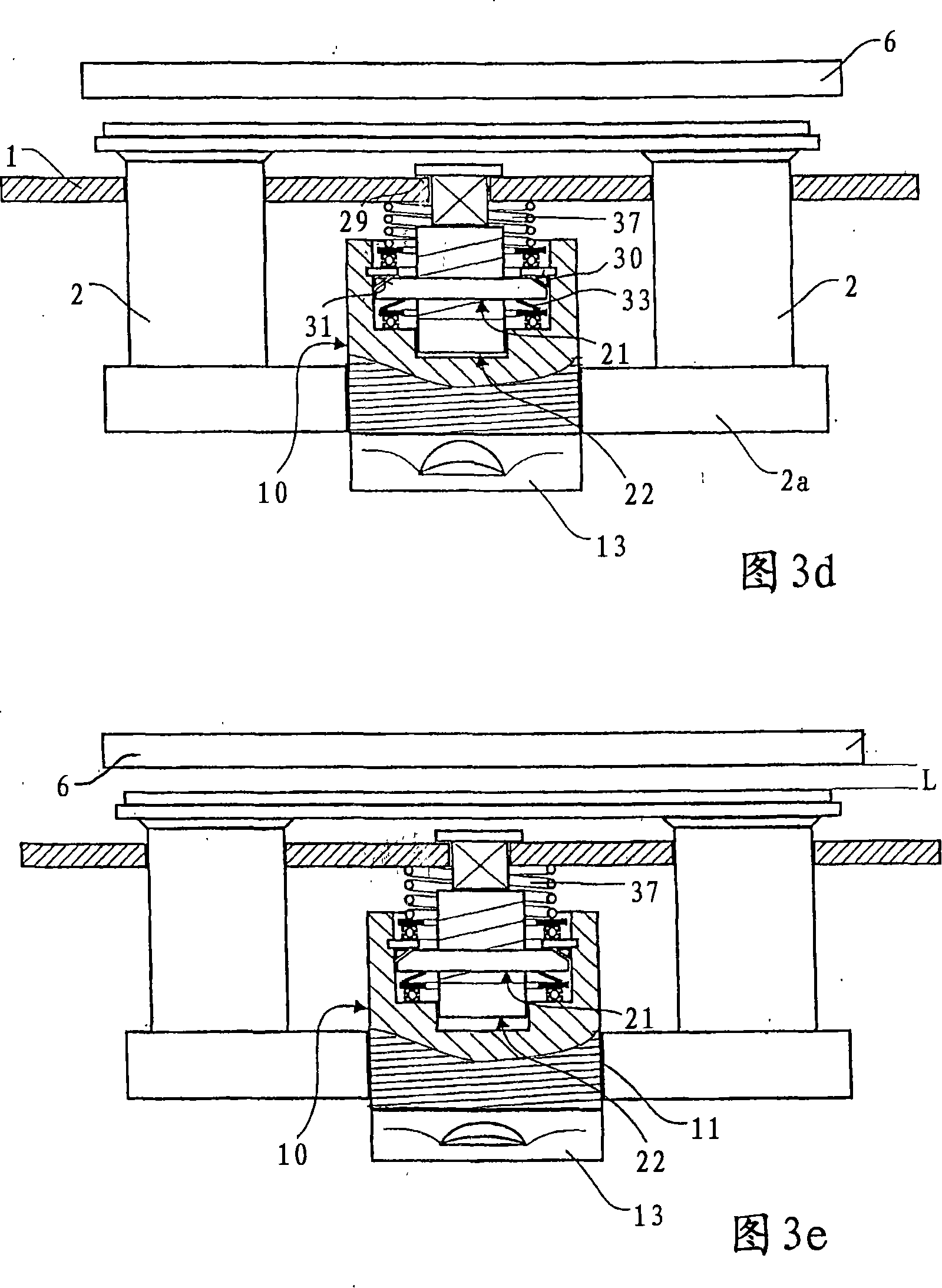
[0044]Disk brakes which operate with an air gap L (FIGS. 2, 3a) on both sides of the brake disk 6 during operation can be equipped with a purely mechanically operating adjustment device which will be described in more detail below. In order to transmit the pressing force generated by the brake cylinder and in particular the compressed-air actuated brake cylinder, a p...


PUM


Abstract

The unit comprises a plunger (2) moved inside a housing (1) towards the brake pad, a device activating the plunger (2) and an adjusting element (10) positioned between the plunger (2) and the activating device. A nut (22) maintains the information about the first moving distance in a particular position, which is transmitted to the adjusting element (10) after returning to its prior position. The plunger (2) is moved in relation to the adjusting element (10). A spindle (21) and a spring-loaded clutch between the nut (22) and the adjusting element (10) are also incorporated.

Description

technical field [0001] The invention relates firstly to a wheel brake with an integrated adjusting device, comprising: a pressure plunger guided in the brake housing and working on the brake pads, a hold-down device for actuating the pressure plunger and a pressure plunger arranged in the Adjusting element in the line of force between the hold-down device inside the brake housing and the pressure plunger, which is screwed to the pressure plunger. [0002] Secondly, the invention relates to a wheel brake with an integrated adjusting device, comprising: a pressure plunger guided in the brake housing and working on the brake lining, a pressing device for actuating the pressure plunger and a pressure plunger arranged in the Adjusting element in the line of force between the hold-down device inside the brake housing and the pressure plunger, which is screwed to the pressure plunger. Background technique [0003] Wheel brakes have been described in many publications which, in add...

Claims


Application Information

Patent Timeline
Patent Type & Authority Applications(China)
IPC IPC(8): F16D65/56F16D55/225
CPCF16D65/183F16D65/60F16D2121/14F16D65/567F16D2125/32
Inventor G·多韦M·佩勒C·阿布特
Owner BPW BERGISCHE ACHSEN KOMMANDITGES
Why Eureka
Try Eureka