Temperature sensor mounting structure and battery module structure

A technology for temperature sensors and battery components, which is applied to battery pack parts, structural parts, electrical components, etc., can solve the problems of difficulty in ensuring the position accuracy of temperature sensors, inability to easily replace temperature sensors, and difficulty in replacing battery component units. Small and lightweight, improved assembly and disassembly workability, and simplified configuration

Active Publication Date: 2008-04-16
HONDA MOTOR CO LTD
View PDF3 Cites 16 Cited by
  • Summary
  • Abstract
  • Description
  • Claims
  • Application Information

AI Technical Summary

Problems solved by technology

In addition, maintenance such as replacement of the temperature sensor cannot be easily performed.
[0008] In addition, when the temperature sensor is closely attached to the battery pack used in a hybrid vehicle or the like, a tape or a heat-shrinkable tube is sometimes used, but even with this structure, it is difficult to ensure the positional accuracy of the temperature sensor, because it is easily affected by the battery cooling. Due to the influence of wind, it is difficult to ensure the temperature detection system
[0009] In addition, in the latter structure of the prior art, wire harnesses are wired through slots that traverse the side covers of a plurality of battery packs, so that the wiring paths tend to be complicated, and the replacement of battery pack units is difficult, etc. The problem of lowered disassembly workability

Method used


Image

  • Temperature sensor mounting structure and battery module structure
  • Temperature sensor mounting structure and battery module structure
  • Temperature sensor mounting structure and battery module structure

Examples


Embodiment 1

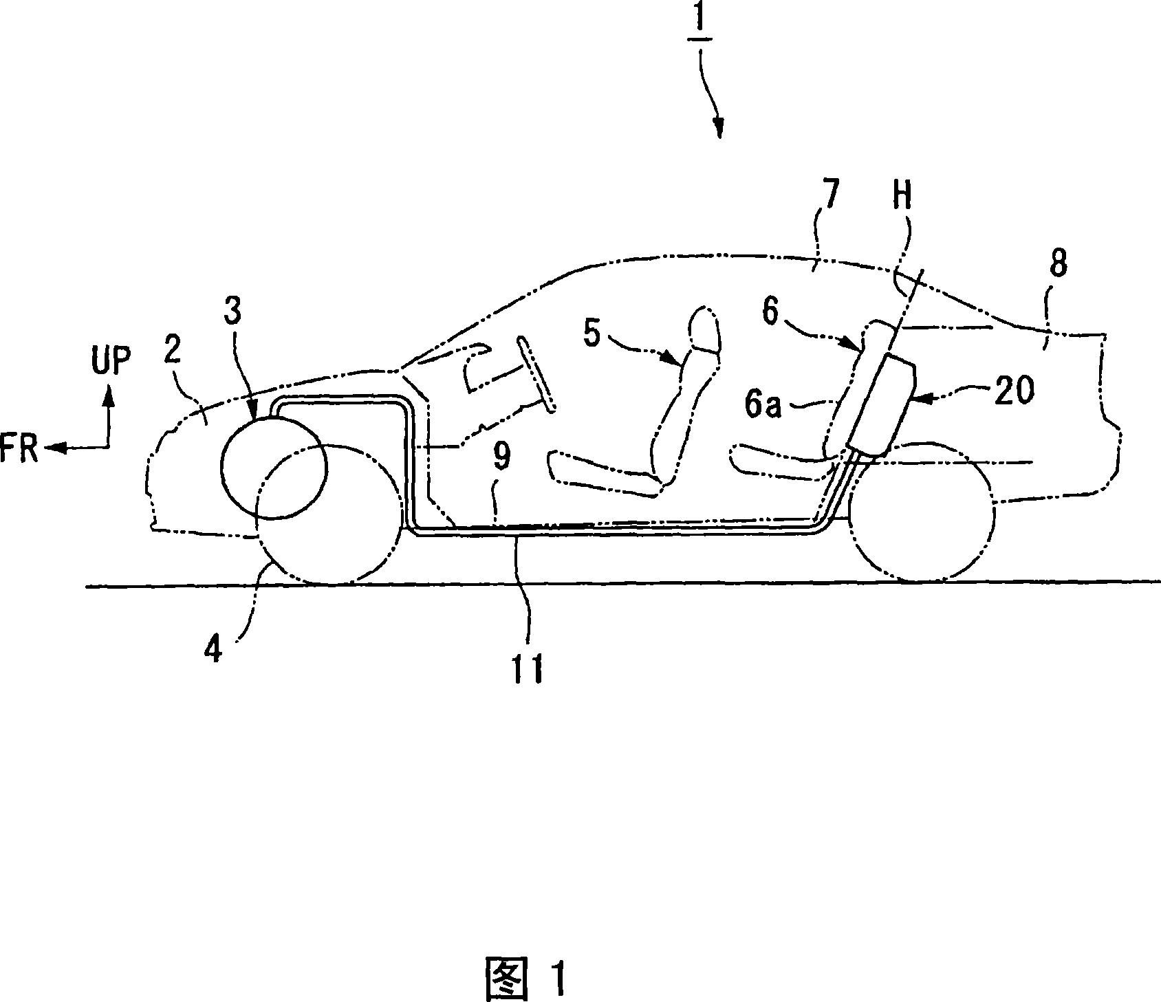
[0072] The vehicle 1 shown in FIG. 1 is a hybrid vehicle, and a motor generator (motor generator) is used to assist in driving an engine as an internal combustion engine, and its kinetic energy can be recovered as electric energy via the motor generator when the vehicle is decelerating. The recovered electrical energy charges the energy storage via the power converter.

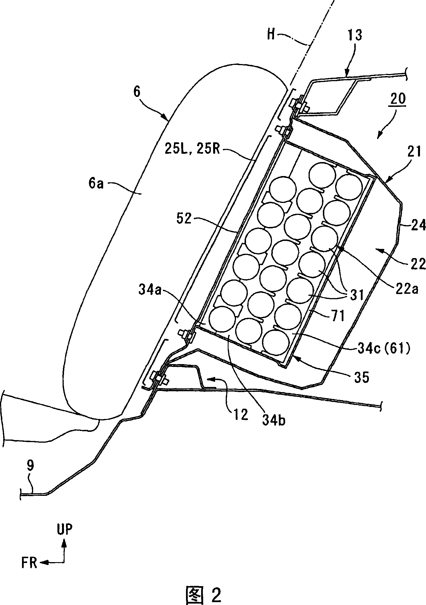
[0073] A power unit 3 in which the engine and a motor generator are arranged in series is mounted in an engine compartment 2 at the front of the vehicle body of the vehicle 1 , and driving force from the power unit 3 is transmitted to front wheels 4 . Behind the engine compartment 2 is provided a compartment 7 having a front seat 5 and a rear seat 6 , and behind the compartment 7 is provided a luggage compartment 8 divided by the compartment 7 and the seat backs 6 a of the rear seat 6 . Further, behind the seat back 6 a of the rear seat 6 (inside the luggage room 8 ), a high-voltage distribution box 20 connect...

Embodiment 2

[0125] Next, a second embodiment of this invention will be described.

[0126] This embodiment is different from the above-mentioned first embodiment in that instead of the sensor cover 80, a sensor cover 100 is used to attach the battery 31, and the same parts as those in the above-mentioned embodiment are given the same reference numerals, and the description thereof will be omitted. .

[0127] The sensor cover 100 shown in FIGS. 13 , 14 , and 15 is made of insulating resin like the sensor cover 80 described above, and is composed of a pair of semicircular bodies 101 and 102 that match the outer circumference of the battery 31 . Ends on one side of the circumferential direction of these semicircular bodies 101 and 102 are connected via, for example, a flexible thin-walled portion 103 (or via a hinge shaft), thereby constituting a hinge portion 104 .

[0128] In the state where the hinge part 104 is disposed on the longitudinal outer side of the battery 31, the semicircular ...

Embodiment 3

[0138] Next, a third embodiment of this invention will be described.

[0139] In this embodiment, the structure is that the wiring harness 128 (corresponding to the wiring 76 ) of the temperature sensor 75 installed on the battery assembly 121A is led out to the end plate 122 of the battery assembly 121A, and the The wire harness fixing device holds the wire harness 128, and the same reference numerals are assigned to the same parts as those in the above-mentioned embodiments, and the description thereof will be omitted.

[0140] As shown in FIGS. 17 and 18 , in a battery pack 121A of this embodiment, the positive and negative electrodes of a pair of batteries 31 are arranged differently from each other, and the ends thereof are connected by end plates 122 . At this time, a predetermined gap is formed between the two batteries 31 . A plurality of such battery packs 121A are arranged in a row, for example, stacked four layers up and down, and one end thereof is properly connec...


PUM


Abstract

A temperature sensor mounting structure for a battery module that is formed by connecting single cells together in series including: a temperature-measuring device that detects the temperature of the battery module; a covering device that covers the temperature-measuring device; and movement-restricting devices that are removably engaged with the battery module and restrict the movement of the covering device.

Description

technical field [0001] The invention relates to a temperature sensor installation structure of a battery assembly and the structure of the battery assembly. [0002] This application claims priority to Japanese Patent Application No. 2005-131858 filed in Japan on April 28, 2005, and Japanese Patent Application No. 2005-174994 filed on June 15, 2005, and the contents thereof are incorporated herein. Background technique [0003] In the past, when a temperature sensor was attached to and fixed on a temperature-measuring object, an adhesive was often used to mount the temperature sensor on the temperature-measuring object (for example, refer to Patent Document 1). [0004] On the other hand, when installing a wire harness for a temperature sensor or the like on a battery pack used in a hybrid vehicle or the like, a groove for wiring the wire harness or the like is sometimes provided on a side cover of a housing housing a plurality of battery packs (for example, Refer to Patent...

Claims


Application Information

Patent Timeline
Patent Type & Authority Applications(China)
IPC IPC(8): H01M2/10B60L11/18B60K1/04H01M10/48
CPCY02T10/7005B60L3/0046B60L11/1872B60L11/1877B60K2001/0416Y02T10/705B60L2260/56B60L11/1879B60K1/04H01M10/482Y02E60/12H01M10/486B60L58/25B60L50/66B60L50/64B60L58/26B60L53/80B60L58/18Y02T10/70Y02T10/7072Y02E60/10
Inventor 澁谷健太郎丸野直树水谷淳松冈俊之
Owner HONDA MOTOR CO LTD
Why Eureka
Try Eureka