Permanent-magnet type electricity loss brake electricity-saving control device

A technology of power-loss brake and power-saving control, which is applied to the components of the brake, the type of the brake, the brake actuator, etc., can solve the problems of consumption, the increase of the surface temperature of the brake, and the high power, so as to reduce the internal temperature and have a simple structure. , the effect of low cost

Inactive Publication Date: 2008-04-30
HARBIN INST OF TECH
View PDF0 Cites 2 Cited by
  • Summary
  • Abstract
  • Description
  • Claims
  • Application Information

AI Technical Summary

Problems solved by technology

[0005] The purpose of the present invention is to overcome the problem that the existing permanent magnet power-off brake consumes a large amount of power (energy) when it is energized, and most of the energy is converted into heat, causing the surface temperature of the brake to rise rapidly

Method used


Image

  • Permanent-magnet type electricity loss brake electricity-saving control device

Examples


specific Embodiment approach 1

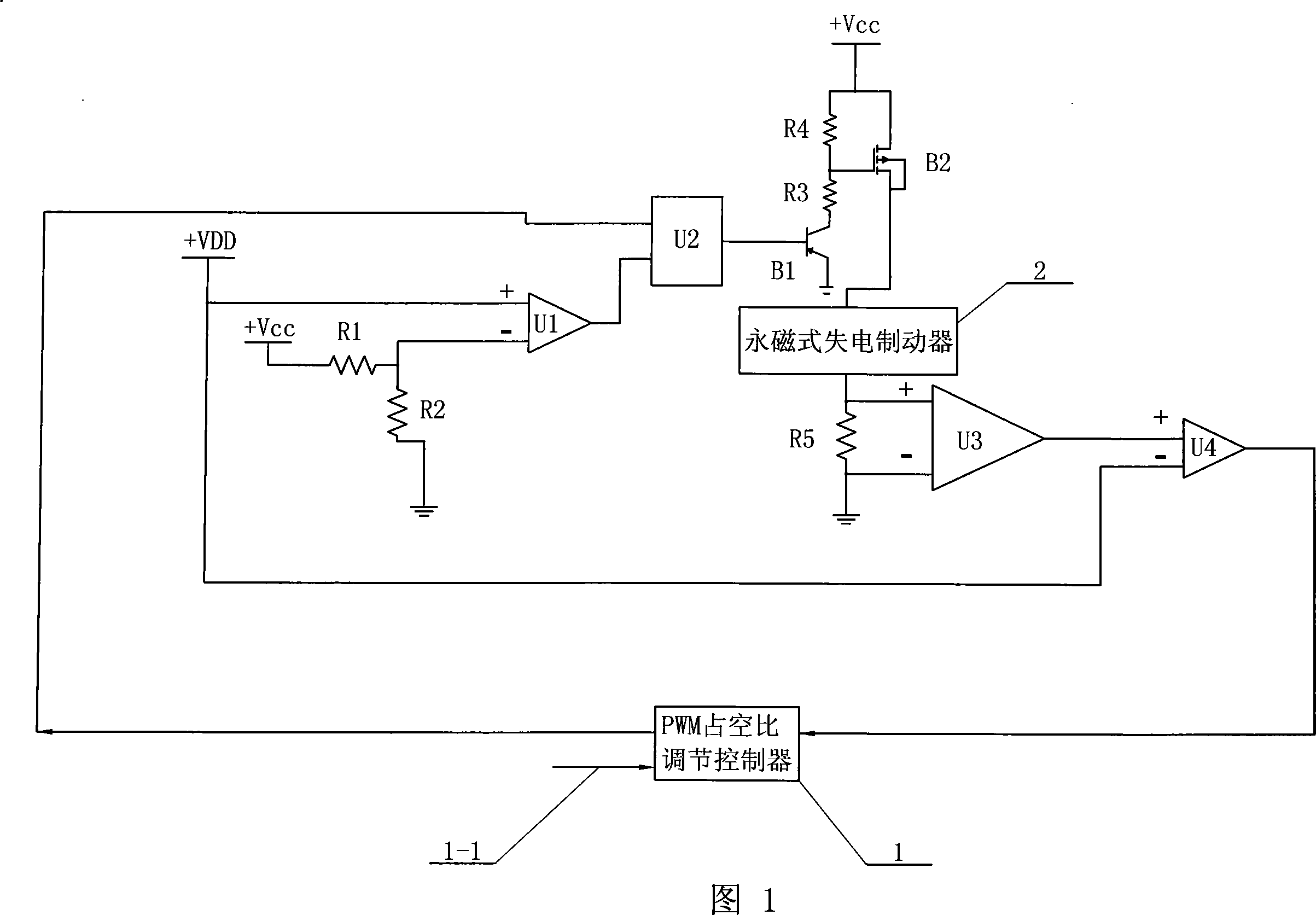
[0016] Specific Embodiment 1: This embodiment is described in conjunction with FIG. 1. This embodiment consists of resistor R1, resistor R2, resistor R3, resistor R4, resistor R5, first operational amplifier comparator U1, two-way AND gate comparator U2, and voltage amplifier U3, the second operational amplifier comparator U4, triode B1, field effect transistor B2, PWM duty ratio adjustment controller 1;

[0017] One end of the resistor R1 is connected to the +Vcc terminal of the power supply, the other end of the resistor R1 and one end of the resistor R2 are connected to the inverting input terminal of the first operational amplifier comparator U1, the other end of the resistor R2 is grounded, and the non-inverting input terminal of the first operational amplifier comparator U1 The input terminal is connected to the inverting input terminal of the second operational amplifier comparator U4 and connected to the reference power +VDD terminal, the output terminal of the first op...


PUM


Abstract

A power saving control device for a permanent-magnet safe brake relates to the technical field of energy conservation and heat-production reducing of permanent-magnet brakes. The invention aims at solving the problem that the prior permanent-magnet safe brake when working after turned on can consume much power (energy), most of which is transformed into heat, quickly raising the surface temperature of the brake. The output end of a PWM duty ratio adjustment controller connects with one input end of the permanent-magnet safe brake via a first operational-amplifier comparer U1, a two-way and-gate comparer U2, a triode B1 and a field-effect transistor B2; the other input end of the permanent-magnet safe brake connects with the input end of the PWM duty ratio adjustment controller via a voltage amplifier U3 and a second operational-amplifier comparer U4; the PWM duty ratio adjustment controller is provided with an electromotor controlling an enabling input end. The invention can automatically adjust the working voltage of the brake according to the distance between the magnet of the permanent-magnet safe brake and a keeper, thereby reducing the power consumption to about 75 percent of the previous amount.

Description

technical field [0001] The invention relates to the technical field of energy saving and calorific value reduction of a permanent magnet brake. Background technique [0002] The development of advanced robots is mainly aimed at high integration, multi-sensor, small weight, high torque output, energy saving and so on. Most of the existing manipulator joints use permanent magnet brushless DC motor drive and harmonic reducer as torque output. However, for most advanced robots, the load moment of the joint is larger than the no-load counter-drive moment of the harmonic reducer. Therefore, most of the robotic arm systems are equipped with power-off brakes, which can effectively ensure that the joints still maintain their posture in the event of a power failure, so as not to cause unexpected movements and damage the equipment. [0003] The dry single-plate friction permanent magnet brake without slip ring mainly includes three parts: brake magnet, electromagnetic coil and armatu...

Claims


Application Information

Patent Timeline
Patent Type & Authority Applications(China)
IPC IPC(8): F16D65/27B25J9/18B25J19/00F16D65/22
Inventor 黄剑斌谢宗武熊根良刘宏孙奎金明河蒋再男刘璐
Owner HARBIN INST OF TECH
Why Eureka
Try Eureka