Method for manufacturing drainage bottle

A manufacturing method and technology of drainage bottles, which are applied to wound drainage devices and suction devices, etc., can solve problems such as the inability to fully guarantee the absolute safety of the drainage bottles, the difficulty in ensuring the airtightness of the drainage bottles, and the loose fit of the seals, etc., to achieve Eliminate hidden dangers of air leakage, avoid trachoma or tiny pores, and have good air tightness

Active Publication Date: 2008-05-07
姚荣平 +2
View PDF0 Cites 5 Cited by
  • Summary
  • Abstract
  • Description
  • Claims
  • Application Information

AI Technical Summary

Problems solved by technology

However, it is also difficult to ensure the airtightness of the manufactured drainage bottle by mechanical means.
This is because the drainage bottle needs to be sterilized with ethylene oxide before it can be put into use. In this sterilization step, due to the high and low changes in temperature, there is a gap in the seal that is mechanically sealed due to the temperature change. air leak hazard
Therefore, even if the non-sterilized drainage bottle can ensure its airtightness, it cannot fully guarantee the absolute safety of the drainage bottle after sterilization.

Method used


Image

  • Method for manufacturing drainage bottle
  • Method for manufacturing drainage bottle
  • Method for manufacturing drainage bottle

Examples


Embodiment 1

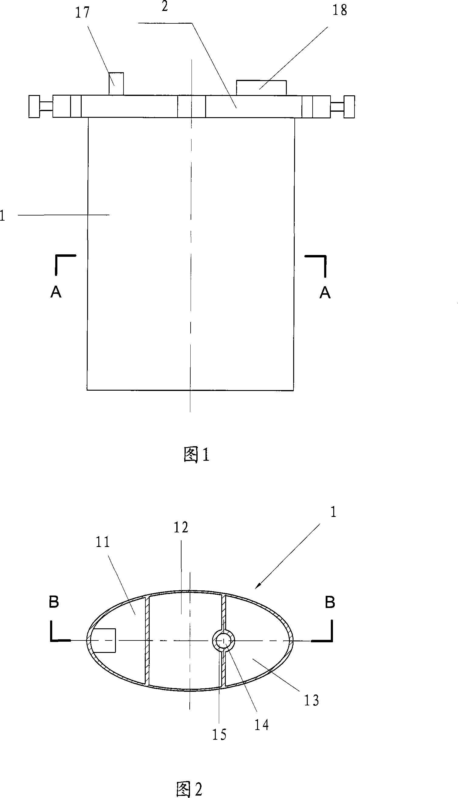
[0029] As shown in FIG. 1 , the drainage bottle implemented according to the present invention includes a bottle body 1 and a bottle cap 2 . The material of the bottle body 1 and the bottle cap 2 is transparent plastic, which is manufactured by injection molding process.

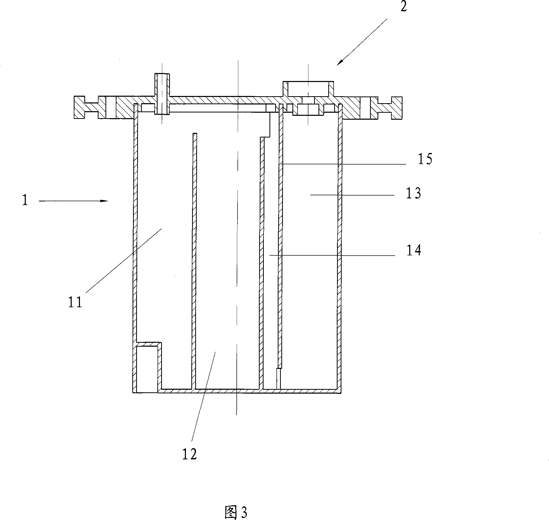
[0030] As shown in Figure 2 and Figure 3, the drainage bottle described in this embodiment is a double-chamber drainage bottle, and the bottle body 1 includes an outer sub-chamber 11 of the accumulation chamber and an inner sub-chamber of the accumulation chamber connected to each other at the upper end. 12. The water seal chamber 13 and the water seal pipe 14, wherein the water seal chamber 13 and the water seal pipe 14 are separated by partitions 15 with openings up and down, the upper edge of the partition 15 is in contact with the bottle The upper edge of the body 1 is at the same height. The bottle cap 2 is provided with a drainage tube inlet 17 for inserting the drainage tube into the sub-cavity 11 ou...

Embodiment 2

[0037] As shown in Figure 6, Embodiment 2 is a three-chamber drainage bottle. As shown in accompanying drawing 7 and accompanying drawing 8, the bottle body of this embodiment includes the sub-chamber 11 outside the accumulating chamber, the sub-chamber 12 inside the accumulating chamber, the water sealing chamber 13, the water sealing tube 14, the pressure regulating chamber 16, and the drainage tube. Inlet 17 , first liquid filling port 18 , second liquid filling port 19 , vent hole 20 . Wherein, the water-seal chamber 13 and the water-seal pipe 14 are separated by partitions 15 with upper and lower openings. Therefore, the shape of the bottle cap 2 in this embodiment is more complicated, and the requirements for the forming process and welding process are higher.

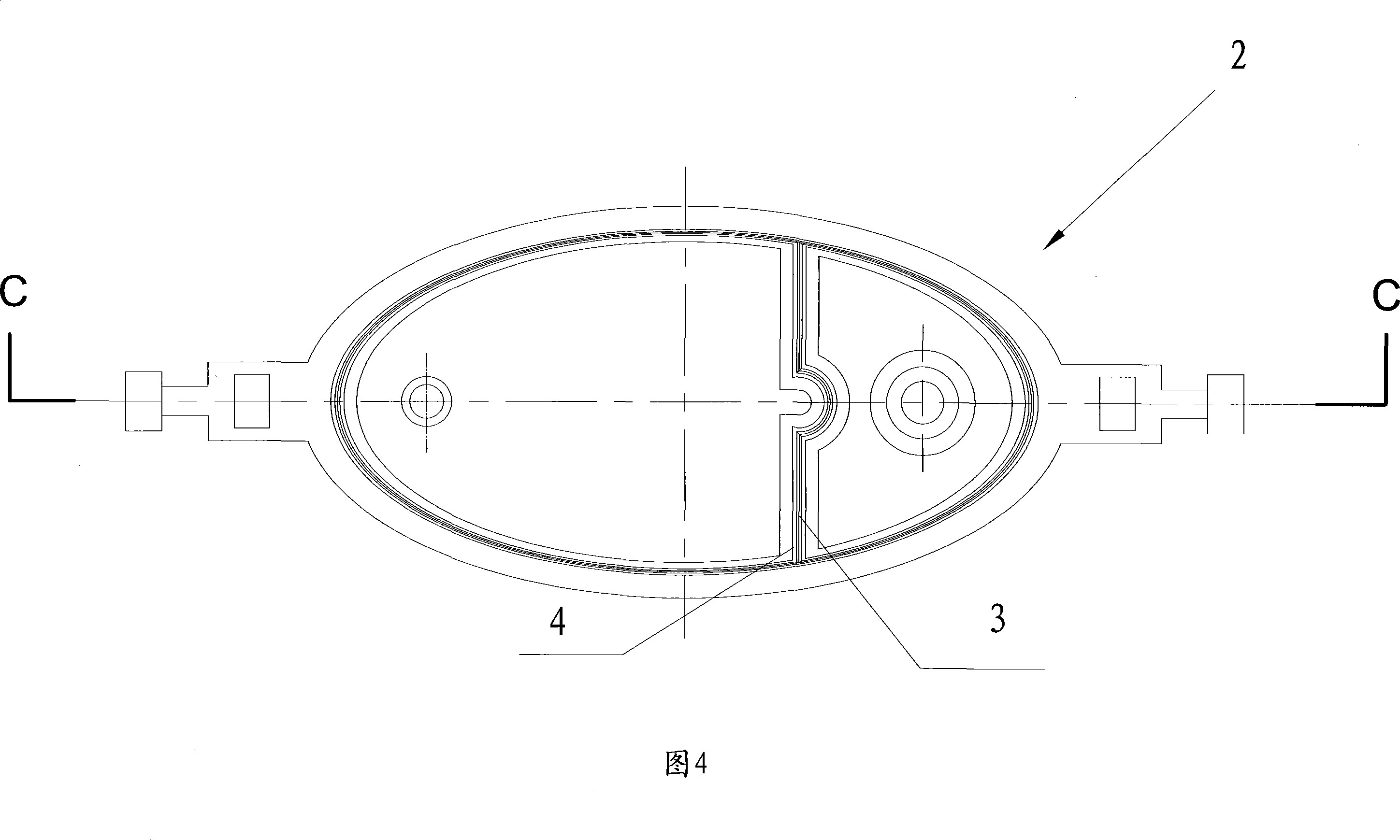
[0038] The welding wire 3 used in this embodiment is also a closed ring that completely corresponds to the shape of the installation groove 4, as shown in Figure 9, and its cross-sectional shape is an equilatera...


PUM


Abstract

The invention relates to a manufacturing method of a drainage bottle. Firstly, a bottle body with an opening and a bottle cap corresponding to the opening shape are respectively produced through the plastic shaping process, and a continuous and closed weld line according with the shape of the upper edge of the bottle body is arranged on the bottle cap; secondly, the bottle cap is fixed and connected at the upper edge of the bottle body by adopting the ultrasonic welding process, and then the bottle cap is covered above the opening in a sealing way. The adopted injection molding process for manufacturing the bottle body, and the bottle cap is simple, the product quality is greatly improved relative to the blow molding process, and the sand holes or micro-air holes generated in the blow molding process are eliminated. The absolute air tightness at the juncture of the bottle body and the bottle cap can be ensured by adopting the ultrasonic welding, and the air leakage hidden danger possibly existing in the mechanical sealing method can be thoroughly stopped.

Description

technical field [0001] The invention relates to a method for manufacturing a drainage bottle. Background technique [0002] Drainage bottle is a kind of commonly used medical device, and the fluid accumulated in the body is drained out of the body through negative pressure bottle to generate negative pressure. The biggest technical difficulty in producing the drainage bottle is to ensure its airtightness. [0003] In the prior art, the vacuum blow molding method is generally used to manufacture the drainage bottle. The drainage bottle generally has 1-2 interconnected cavities, and each cavity is provided with a narrow through hole for gas or liquid exchange with the outside world. Through the through holes, independent cavities are manufactured by blow molding technology, and then the cavities are connected to each other. Or use a multi-cavity blow molding process to blow mold each cavity in the same mold at one time. [0004] Adopting the above-mentioned method to manuf...

Claims


Application Information

Patent Timeline
Patent Type & Authority Applications(China)
IPC IPC(8): B29C69/00B29C65/08B29C45/00A61M1/00A61M27/00
Inventor 马海涛姚荣平汤健华
Owner 姚荣平
Why Eureka
Try Eureka