Sun tracing apparatus

A sun tracking and outer frame technology, applied in the field of solar energy tracking, can solve the problems of being unable to get rid of the intermediate shaft transmission mode, unreasonable power matching, and excessive bearing of transmission parts

Inactive Publication Date: 2008-05-07
刘奇灵
View PDF1 Cites 29 Cited by
  • Summary
  • Abstract
  • Description
  • Claims
  • Application Information

AI Technical Summary

Problems solved by technology

It can be seen from this that in order to generate a rotational torque that can compete with the wind force on the intermediate shaft, it is necessary to increase the driving power, which will lead to unreasonable power matching, resulting in waste of electric energy, and even excessive bearing of the transmission parts. , resulting in metal damage
Due to the transmission of the intermediate shaft, the circle is driven by the center of the circle. Due to the magnification of the umbrella, various weak angular displacement errors in the central area will be magnified several times or even dozens of times in the side area of ​​​​the umbrella, resulting in a decrease in tracking accuracy.
Especially it is difficult to overcome the disturbance error caused by the transmission clearance
Therefore, designing according to traditional ideas cannot get rid of the transmission mode of the intermediate shaft, and the existence of the intermediate shaft is the root cause of many unfavorable designs

Method used


Image

  • Sun tracing apparatus
  • Sun tracing apparatus
  • Sun tracing apparatus

Examples


Embodiment 1

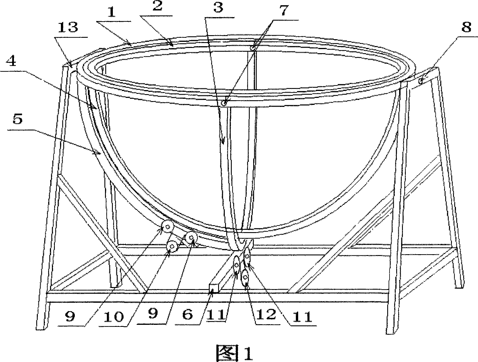
[0031] Figure 1 is a circular sun tracking device whose fixed bracket is supported horizontally. This type is mainly used for small and medium-sized circular spotlights and light tracking. Figure 1 adopts the chain transmission mode, and its tracking process is as follows: in terms of external rotation angle, the azimuth angle offset signal is amplified to drive a stepping motor or a reduction motor, and the motor drives the chain gear 12 to rotate, and the sprocket 12 drives the chain to move. Because two ends of the chain are respectively fixed on the two ends of the outer frame drive half-wheel 3, under the transmission cooperation of two chain gears 11, along with the chain moves, the traction outer frame drive half-wheel 3 rotates. Because the outer frame transmission half-wheel 3 is integrated with the outer frame 1, the outer frame 1 and the outer frame transmission half-wheel 3 rotate together. This constitutes the outer rotation angle rotation of the outer frame. At...

Embodiment 2

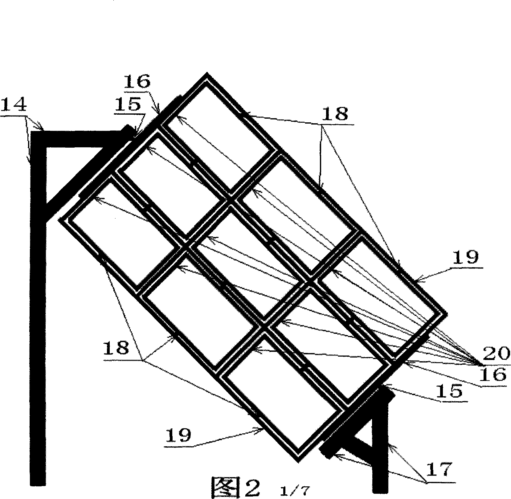
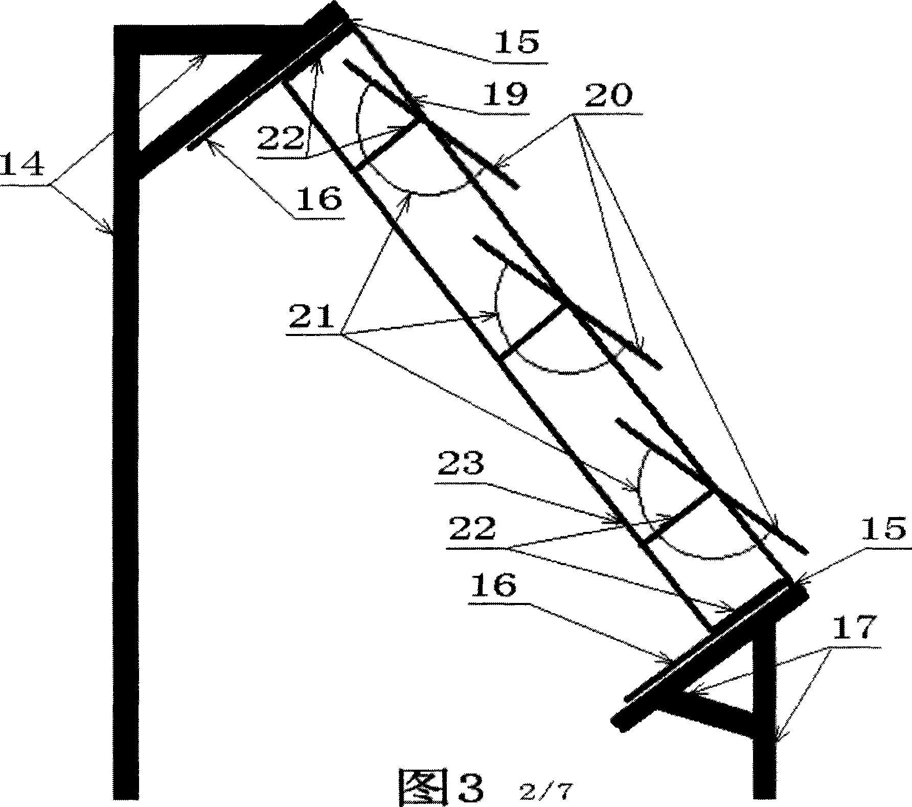
[0033] Figure 2 shows a rectangular slope sun tracking device. This design is specially designed for medium and large rectangular heliostat tracking. Its fixed bracket adopts a slope type, low in the south and high in the north, and supported in the north and south. This is due to the southward movement of the sun in the northern hemisphere. Its purpose is to reduce the obstruction of the light path by the bracket and make the space utilization more smooth.

[0034]The transmission mode of the inner frame of Fig. 2 is shown in Fig. 8. It is a hybrid transmission mode. The gear motor drives the worm 28 to rotate, and the worm 28 drives the three worm wheels 27 to rotate. The three worm wheels 27 are respectively connected to three rotating shafts 26, and each rotating shaft is respectively Drive three shaft transmission wheels 25 to rotate, and each transmission wheel drives an inner frame transmission half-wheel 21 to rotate. In the case of a large number of sub-mirrors, th...

Embodiment 3

[0037] Fig. 11 is a perspective view of a rectangular slope type sun tracking device. This type is suitable for all kinds of tracking of small and medium-sized rectangular daylighting devices. The slope angle can be designed according to the change of the local solar elevation angle, in order to maximize the unobstructed movement space of the daylighting device. What is different from Fig. 2 is that the inner frame in Fig. 11 is a rectangular single spin frame. This type is simple in structure, easy to manufacture, low in cost, and strong in wind resistance. It is suitable for applications such as solar cookers, solar boilers, solar photovoltaic cells, solar thermal power, and small and medium-sized heliostats. Its two-dimensional tracking principle is the same as that in Figure 1.


PUM


Abstract

The invention provides a sun-tracking device with an external rotating angle and an internal rotating angle, belonging to the technical field of solar energy utilization and track. The invention is characterized in that: an inner gimbal rotating shaft is connected with the outer gimbal, the outer gimbal rotating shaft is connected with a bracket; the inner gimbal, the outer gimbal and a fixed bolster are connected with each other through a shafting forming an outer gimbal rolling shaft which can rotate as the external rotating angle, the inner gimbal can rotate as the internal rotating angle and the external rotating angle, moreover; a rotating half wheel and a rotating driving bracket are arranged on the inner gimbal and the outer gimbal respectively, controlling the tracking trajectory in a hemispheric spherical surface range. The invention has the advantages of simple structure, low cost, strong wind resistance, suitability for concentrating light, lighting, fixing sun and other kinds of tracking, and suitability for tracking control of optics and real-time programs.

Description

1. Technical field [0001] The invention relates to solar energy utilization tracking technology, which is one of the key technologies of solar energy utilization. 2. Background technology [0002] At present, the sun tracking device is mainly designed using the tracking idea of ​​elevation angle plus azimuth angle. The altitude angle is vertical rotation, the azimuth angle is horizontal rotation, and the two-dimensional combination constitutes spherical tracking. Designing according to this traditional idea, it is impossible to make vertical rotation and horizontal rotation, the centers of these two rotations coincide directly on an origin. Therefore, between the two centers, with the help of one or two vertically intersecting intermediate axes, one of the center points or two center points needs to be translated along the extension direction of the axis to the virtual origin where the two center points intersect for coincidence. This constitutes a two-dimensional combined...

Claims


Application Information

Patent Timeline
Patent Type & Authority Applications(China)
IPC IPC(8): F24J2/38H02N6/00G02B7/198H02S20/32
CPCY02E10/47F24J2/5424F24S30/455F24S2030/134Y02E10/50
Inventor 刘奇灵
Owner 刘奇灵
Why Eureka
Try Eureka