Broad-band back-reflection helical antenna

A helical antenna and wide-band technology, which is applied in the direction of antenna, radiation element structure, electrical components, etc., can solve the problems that the antenna bandwidth cannot be met, the antenna bandwidth is narrow, and the cross-polarization component increases, so as to improve the aperture utilization Efficiency, good consistency, and simple structure

Active Publication Date: 2008-05-07
BEIJING SATELLITE INFORMATION ENG RES INST
View PDF2 Cites 13 Cited by
  • Summary
  • Abstract
  • Description
  • Claims
  • Application Information

AI Technical Summary

Problems solved by technology

However, this type of antenna has three disadvantages: First, the antenna bandwidth is relatively narrow, generally about 10% of the relative bandwidth. Narrow, which cannot meet the requirements of modern communication capacity for antenna bandwidth; second, the circular polarization characteristics of the antenna can hardly be satisfied in a wide frequency range, and only have a better circular polarization axis ratio in a narrower frequency range , the ratio of the circular polarization axis becomes worse in the broadband range, even greater than 3dB, and the cross-polarization component increases sharply, which cannot meet the requirements of modern communication for the circular polarization characteristics of the antenna, because the advanced and efficient modulation method of modern digital communication has a large impact on The axial ratio and cross-polarization of circularly polarized antennas have strict requirem

Method used


Image

  • Broad-band back-reflection helical antenna
  • Broad-band back-reflection helical antenna

Examples


Embodiment Construction

[0024] The present invention will be further described below in conjunction with accompanying drawing.

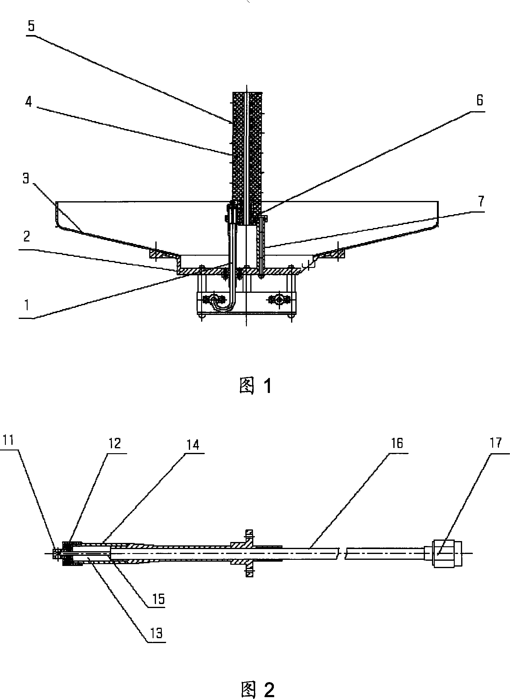
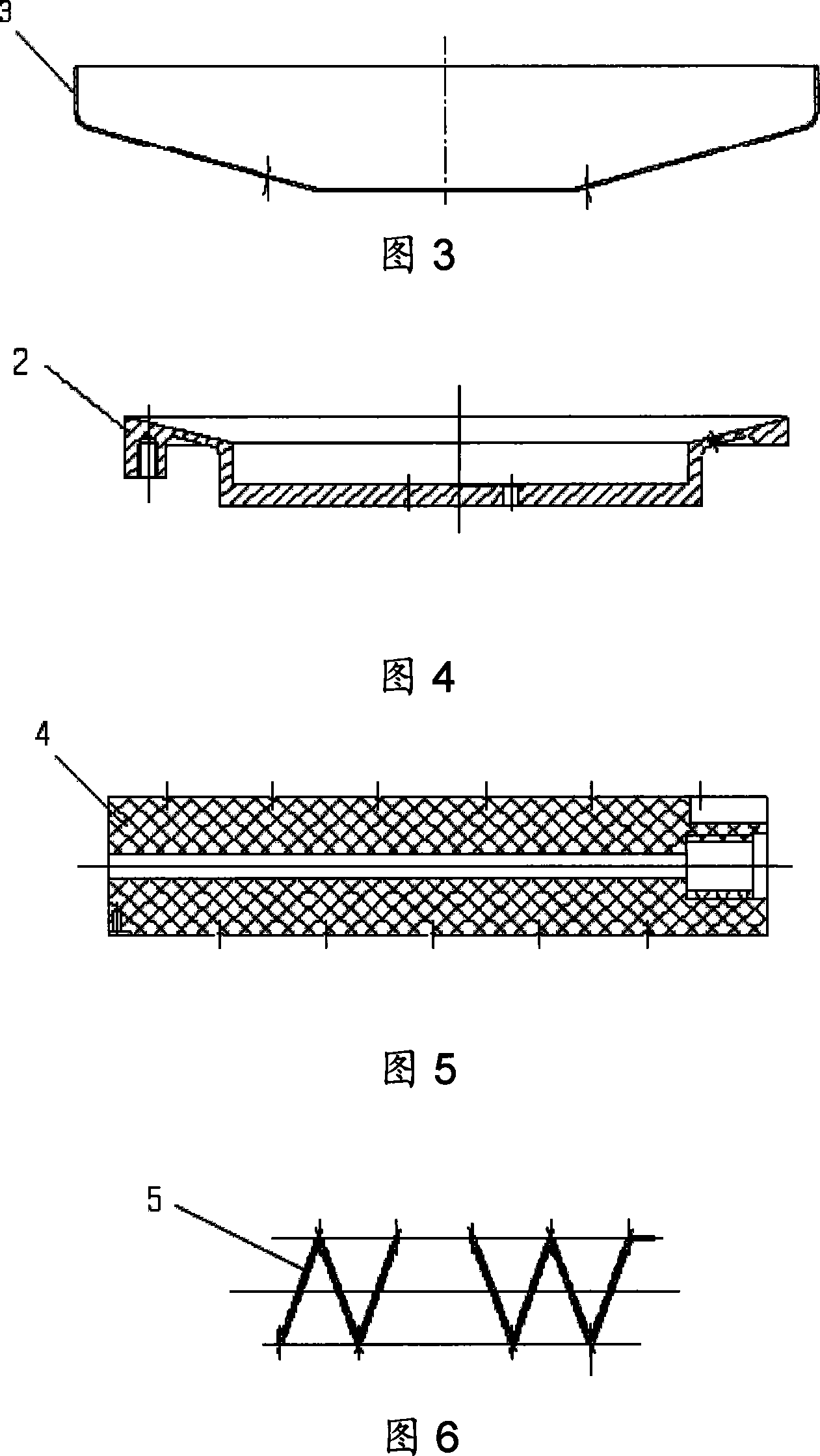
[0025] As shown in Figures 1 and 2, the broadband backfiring helical antenna of the present invention includes a feed assembly 1, a primary radiator and a reflection cavity. The feed assembly 1 is composed of a connecting column 11, a transition feed medium 12, a transform feed medium 13, a feed outer conductor 14, a feed inner conductor 15, a cable 16, and an electrical connector 17; the primary radiator is composed of a metal helical wire 5 is formed around the helical medium support 4; the reflection cavity includes a reflector tray 2 and a reflection cavity 3; the helix dielectric support 4 is fixedly connected to the center of the reflector tray 2, and the feed assembly 1 is connected to the reflector tray 2, The feed inner conductor 15 is connected to the lower end of the helical wire 5 through the connecting column 11 . Connect the spiral support 4 and the shaped re...


PUM


Abstract

The present invention discloses a wide-band backfire spiral antenna, including a feeder module (1), a primary radiator and a reflection cavity. The feeder module (1) consists of a connecting column (11), a transitional feeding medium (12), a conversion feeding medium (13), an external feeding conductor (14), an internal feeding conductor (15), a cable (16) and an electric connector (17), which are connected accordingly. The primary radiator is formed by winding a metal spiral wire (5) on the medium support of the spiral wire (4). The reflection cavity includes a reflection tray (2) and a reflection cavity (3). The filing medium in a transforming feed medium (13) is air. The reflection cavity is the ode-shaped reflection cavity. The antenna of the invention can widen the bandwidth, and the relative bandwidth reaches to 30% above. And the antenna has the advantages of simple structure and good consistency. At the same time, a technique of combining the backfire spiral with the ode-shaped reflection cavity is adopted to improve the aperture utilization ration of the antenna. And the gain of the antenna reaches to 10dB above.

Description

technical field [0001] The invention relates to antenna technology in the field of wireless communication, in particular to an antenna with high requirements on broadband characteristics and circular polarization characteristics. Background technique [0002] There are relevant literature reports on backfiring antennas with oscillators or crossed oscillators as primary radiators. This type of antenna is generally composed of two parts: a primary radiator and a cylindrical reflective cavity. The cylindrical reflective cavity converts the electromagnetic waves back-radiated by the primary radiator into Electromagnetic waves that radiate forward with high gain. However, this type of antenna has three disadvantages: First, the antenna bandwidth is relatively narrow, generally about 10% of the relative bandwidth. Narrow, which cannot meet the requirements of modern communication capacity for antenna bandwidth; second, the circular polarization characteristics of the antenna can ...

Claims


Application Information

Patent Timeline
IPC IPC(8): H01Q19/10H01Q1/36
Inventor 董涛郭文嘉李景贵张胜辉王兵葛琳
Owner BEIJING SATELLITE INFORMATION ENG RES INST
Why Eureka
Try Eureka