Driving means for combing machine nipper

A driving device and combing machine technology, which is applied in the direction of combing machines, textiles and papermaking, fiber processing, etc., to achieve the effect of improving rapid response ability, improving motion accuracy and efficiency

Inactive Publication Date: 2008-05-14
ZHEJIANG UNIV
View PDF0 Cites 6 Cited by
  • Summary
  • Abstract
  • Description
  • Claims
  • Application Information

AI Technical Summary

Problems solved by technology

[0003] The purpose of this invention is to provide a kind of driving device of combing machine nipper, the speed of any position of nipper can be controlled easily, make the motion track of nipper satisfy the driving device of combing machine nipper part motion requirement of nipper, In order to solve the deficiencies in the transmission device of the nipper part of the existing combing machine

Method used


Image

  • Driving means for combing machine nipper

Examples


Embodiment Construction

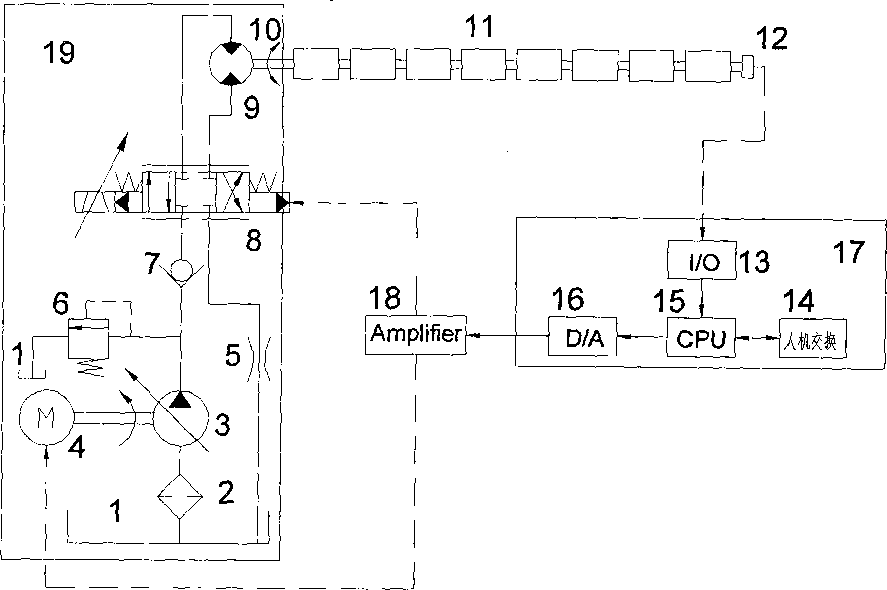
[0011] As shown in the drawings, the present invention includes servo motor 4, open hydraulic system 19, nipper 11, nipper pendulum shaft 10, transmission control system 17 and electronic amplifier 18; described open hydraulic system 19 consists of oil tank 1, Coarse filter 2, one-way variable hydraulic pump 3, throttle valve 5, safety relief valve 6, one-way valve 7, three-position four-way electro-hydraulic servo valve 8 and two-way quantitative hydraulic motor 9, one-way variable hydraulic pump 3 The input end of the servomotor 4 is connected to the output end of the two-way quantitative hydraulic motor 9, and the output end of the bidirectional quantitative hydraulic motor 9 is connected to one end of the nipper pendulum shaft 10, and the other end of the nipper pendulum shaft 10 is connected to the speed sensor 12, and the speed sensor 12 is connected to the transmission control system 17 . The output terminal of the transmission control system 17 is connected to the inpu...


PUM


Abstract

The invention discloses a driving device for a combing machine nipper. Including nipper, nipper pendulum shaft, three-position four-way proportional solenoid valve, two-way quantitative hydraulic motor, coarse filter, one-way variable hydraulic pump, safety overflow valve, one-way valve, throttle valve, servo motor, speed sensor and transmission control system. The above-mentioned execution component is driven by the servo motor under the control of the transmission control system through the open hydraulic system to drive the nipper pendulum shaft to make the nipper move according to the predetermined curve rule, thus constituting the driving device of the comber nipper. The invention adopts the combination scheme of the transmission control system and the open hydraulic system to improve the quick response capability of the nipper drive device of the combing machine, thereby improving the movement accuracy and efficiency of the nipper part of the combing machine.

Description

technical field [0001] The invention relates to textile machinery equipment, in particular to a driving device for a combing machine nipper. Background technique [0002] The traditional combing machine nipper transmission device is composed of two sets of four-bar linkage mechanisms, the crank slider linkage mechanism and the rocker linkage mechanism. There are many meshing points in the movement, and the precision is poor. The parts of the mechanism require high precision in manufacturing and installation, and it is difficult to adapt to high-speed reciprocating rotation. For the spinning process of various cotton fibers, its applicability and versatility are poor. . At present, the new servo motor drives the driving device of the comber nipper, although the mechanical transmission structure with complex structure is eliminated, but due to the large load inertia of the nipper part, the servo motor needs to transmit a large torque and consumes a lot of power, while the com...

Claims


Application Information

Patent Timeline
Patent Type & Authority Applications(China)
IPC IPC(8): D01G19/16D01G19/26
Inventor 李伟张大海鲍先兵
Owner ZHEJIANG UNIV
Why Eureka
Try Eureka