
Saw splitter

A demultiplexer and filter technology, applied in the directions of printed inductors, electrical components, impedance networks, etc., can solve the problem of undisclosed electrode structure, and achieve the effect of reducing the area and occupying a smaller area.

Active Publication Date: 2008-05-14
MURATA MFG CO LTD
View PDF2 Cites 5 Cited by
  • Summary
  • Abstract
  • Description
  • Claims
  • Application Information

AI Technical Summary

Problems solved by technology

Therefore, Patent Document 2 shows a structure in which spiral electrodes are formed on a plurality of layers, but does not disclose an electrode structure that can be used as a bridge inductor in a SAW duplexer.

Method used


Image

  • Saw splitter
  • Saw splitter
  • Saw splitter

Examples


Embodiment Construction

[0054] Hereinafter, specific embodiments of the present invention will be described with reference to the drawings to clarify the present invention.

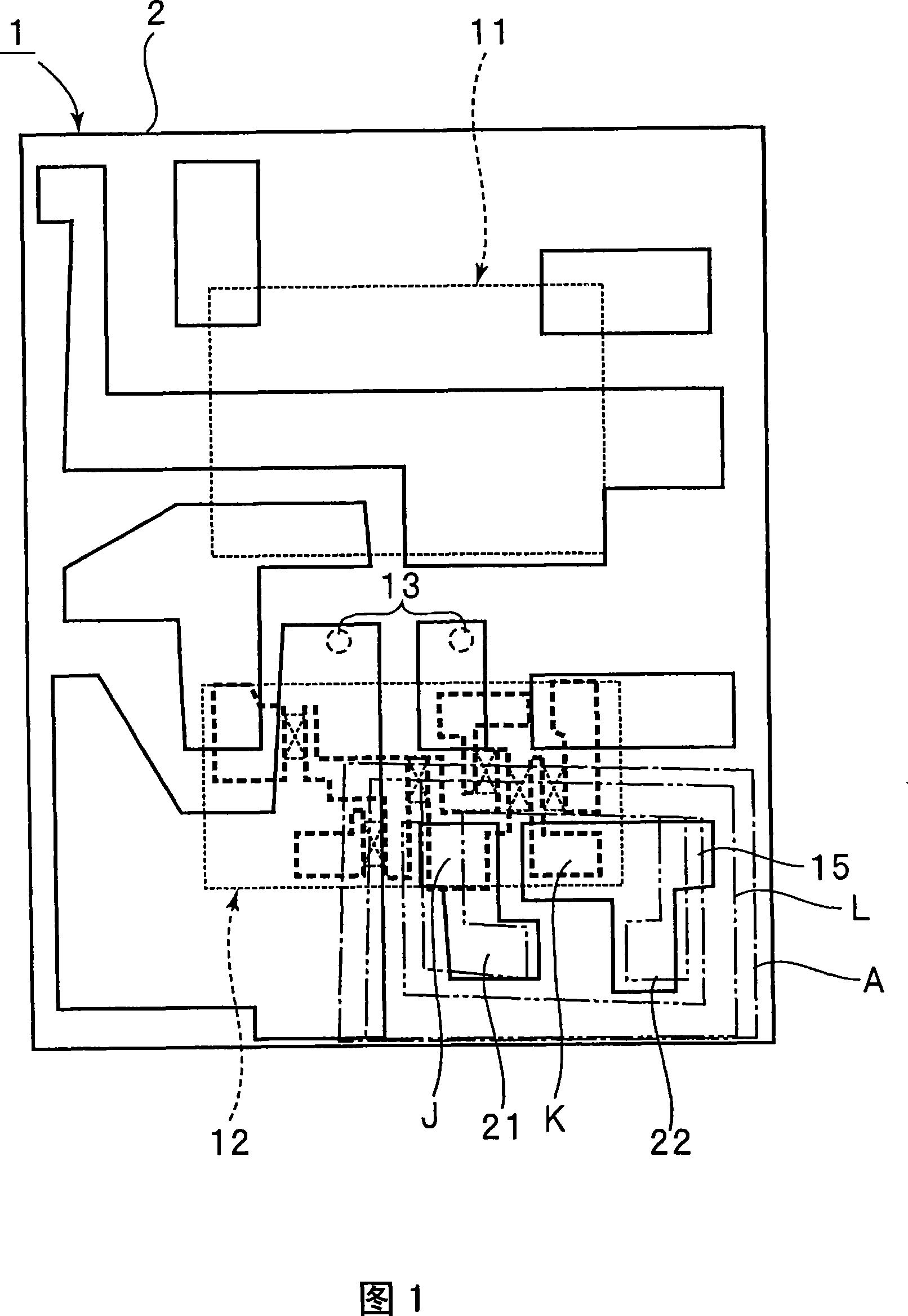
[0055] FIG. 1 is a schematic plan view showing a SAW duplexer according to an embodiment of the present invention.

[0056] The SAW splitter 1 has a multilayer packaging substrate 2 . The multilayer packaging substrate 2 is formed of a multilayer ceramic substrate. However, the multilayer package substrate 2 may also be formed using an insulating material other than ceramics.

[0057] On the multilayer package substrate 2 , as indicated by the dotted line, the first SAW filter chip 11 and the second filter chip 12 are mounted by flip-chip bonding. That is, the SAW filter chips 11 and 12 are mounted on the upper surface of the multilayer package substrate 2 using metal bumps. In FIG. 1, the outlines of the SAW filter chips 11 and 12 are indicated by dotted lines as described above.

[0058] The illustrated electrodes are form...


PUM


Abstract

Provided is an SAW divider, which can constitute a bridged inductor without increasing the area of a package substrate and which not only has excellent filter characteristics but also can promote its size reduction. The SAW divider (1) comprises a first SAW filter having a relatively low band-pass frequency, and a second SAW filter having a relatively high band-pass filter. The first and second SAW filters have a ladder-type circuit constitution. In parallel with at least one series-arm resonator of the second SAW filter, there is connected a bridged inductor, which has a coil-wound portion constituted in a multilayer package substrate. This coil-wound portion is constituted by connecting first to third wiring lines (23, 26 and 29) of first to third layers by via-hole conductors. Inside of the coil-wound portion, there are arranged first, third and fifth via hole conductors (24, 27 and 30), which constitute the return portions of the coil.

Description

technical field [0001] The present invention relates to a SAW demultiplexer formed by using first and second SAW filters with different passbands, in particular to the first and second SAW filters having a ladder loop structure, and in at least one SAW filter, the The SAW splitter of the bridge inductor is connected in parallel to the series arm resonator. Background technique [0002] In recent years, SAW duplexers configured using first and second SAW filters having different passbands have been widely used in mobile phones. An example of such a SAW demultiplexer is disclosed in Patent Document 1 below. [0003] FIG. 16 is a diagram showing a circuit configuration of a SAW duplexer described in Patent Document 1. As shown in FIG. The SAW demultiplexer 101 is connected to the antenna 102 . That is, the first SAW filter 111 and the second SAW filter 112 are connected to the antenna 102 . The first SAW filter 111 and the second SAW filter 112 have different passbands. In...

Claims


Application Information

Patent Timeline
Patent Type & Authority Applications(China)
IPC IPC(8): H03H9/72H03H9/64H03H9/25
CPCH03H9/72H03H9/0576H03H9/725H01F2017/002
Inventor 大村正志谷口典生
Owner MURATA MFG CO LTD
Features
  • Generate Ideas
  • Intellectual Property
  • Life Sciences
  • Materials
  • Tech Scout
  • Unparalleled Data Quality
  • Higher Quality Content
  • 60% Fewer Hallucinations
Learn More