Magnetic drive high speed turbocharger

A technology of turbocharger and magnetic transmission, which is applied in the direction of machines/engines, electromechanical transmissions, liquid fuel engines, etc. It can solve the problems of difficult sealing and gas transportation, and achieve the effect of eliminating gas leakage

Inactive Publication Date: 2008-05-21
SOUTH CHINA UNIV OF TECH
View PDF0 Cites 7 Cited by
  • Summary
  • Abstract
  • Description
  • Claims
  • Application Information

AI Technical Summary

Problems solved by technology

It is particularly difficult to seal when applied to highly permeable gases (such as hydrogen)
At the same time, due to the mutual friction between the sealing materials, the sealing parts need to be lubricated and cooled, and it is difficult to meet the needs of gas transportation with high requirements on gas quality and sealing

Method used


Image

  • Magnetic drive high speed turbocharger

Examples


Embodiment Construction

[0019] The present invention will be further described in detail below in conjunction with the embodiments and accompanying drawings, but the protection scope of the present invention is not limited to the scope described in the embodiments.

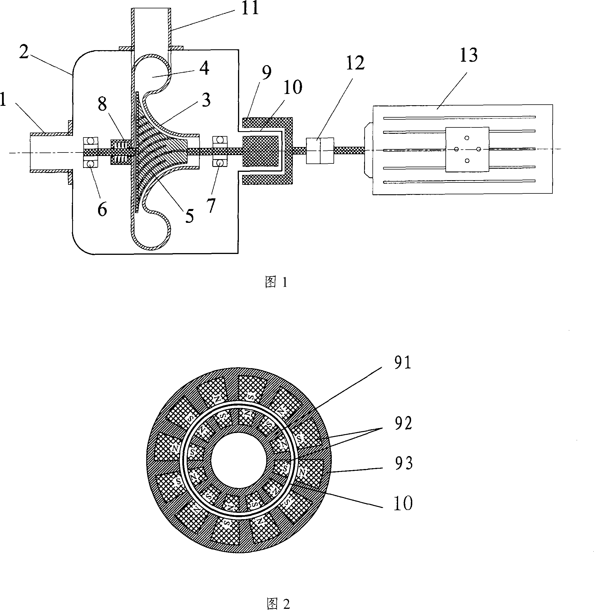
[0020] As shown in Figure 1, a magnetic drive high-speed turbocharger includes a volute 3, a turbine rotor 5, a diffuser tank 4, a housing 2, an air outlet 11, a high-speed motor 13 and a magnetic coupling 9, and the turbine rotor 5 is located at The center of the volute 3, the outer side of the turbine rotor 5 in the volute 3 is a diffuser groove 4, the diffuser groove 4 communicates with the air outlet 11, the volute 3, the turbine rotor 5, and the diffuser groove 4 are arranged in the housing 1, and the housing The body 2 is provided with an air inlet 1 and an air outlet 11. The magnetic coupling 9 is composed of an outer rotor assembly and an inner rotor assembly. The outer rotor assembly and the inner rotor assembly are separated by ...


PUM


Abstract

The present invention discloses a magnetic drive high speed turbocharger, consisting of a turbo shell, a turbo rotor, a diffusing groove, a shell, an air inlet, an air outlet, a high-speed motor and a magnetic coupler. The coupler is composed of an external rotor assembly and an internal rotor assembly; the two assemblies are divided by an isolation cover which is fixed on the shell forming a sealed chamber with the shell. Besides, the external rotor assembly is connected with the high-speed motor and the internal rotor assembly is connected with the turbo rotor. The invention adopts the magnetic coupler drive, the whole pressure-improving component is arranged in a sealed shell, which eliminates sealing problems caused by dynamic sealing with no need of lubrication and cooling. The compressor is suitable for the high purity gas which has strict requirements for sealing, flammable and explosible, poisonous and baneful.

Description

technical field [0001] The invention relates to a turbocharger used for medium pressure differential gas transmission, especially for gas transmission occasions with high requirements on gas quality and sealing. Background technique [0002] Turbine compressor is the most widely used gas booster equipment among turbine compressors, and it is widely used in various sectors of the national economy, especially in mining, metallurgy, petroleum, chemical industry, energy and other fields. However, since the boost value of the turbocharger is proportional to the square of the turbine edge linear velocity, in order to obtain a larger boost, it is necessary to use a larger turbine diameter and a higher speed, or to use multi-stage turbines in series, and the manufacturing cost higher. Therefore, turbochargers are mostly used in large-flow gas delivery occasions. The equipment used for gas transportation with small flow rate and medium pressure differe...

Claims


Application Information

Patent Timeline
IPC IPC(8): F04D25/06F04D29/05H02K51/00F04D29/056F04D29/10
Inventor 朱冬生曾力丁
Owner SOUTH CHINA UNIV OF TECH
Why Eureka
Try Eureka