

Extrusion pressing mould plate component and its stalk rail tank compression molding forming device, and molding machine
A technology of extruding templates and track grooves, which is applied to household components, other household appliances, household appliances, etc., can solve the problems of low quality, low density, and low level of mechanization in the furnace, and achieve high production efficiency, long service life, adaptable effect
- Summary
- Abstract
- Description
- Claims
- Application Information
AI Technical Summary
Problems solved by technology
Method used
Image

Examples
Embodiment 1
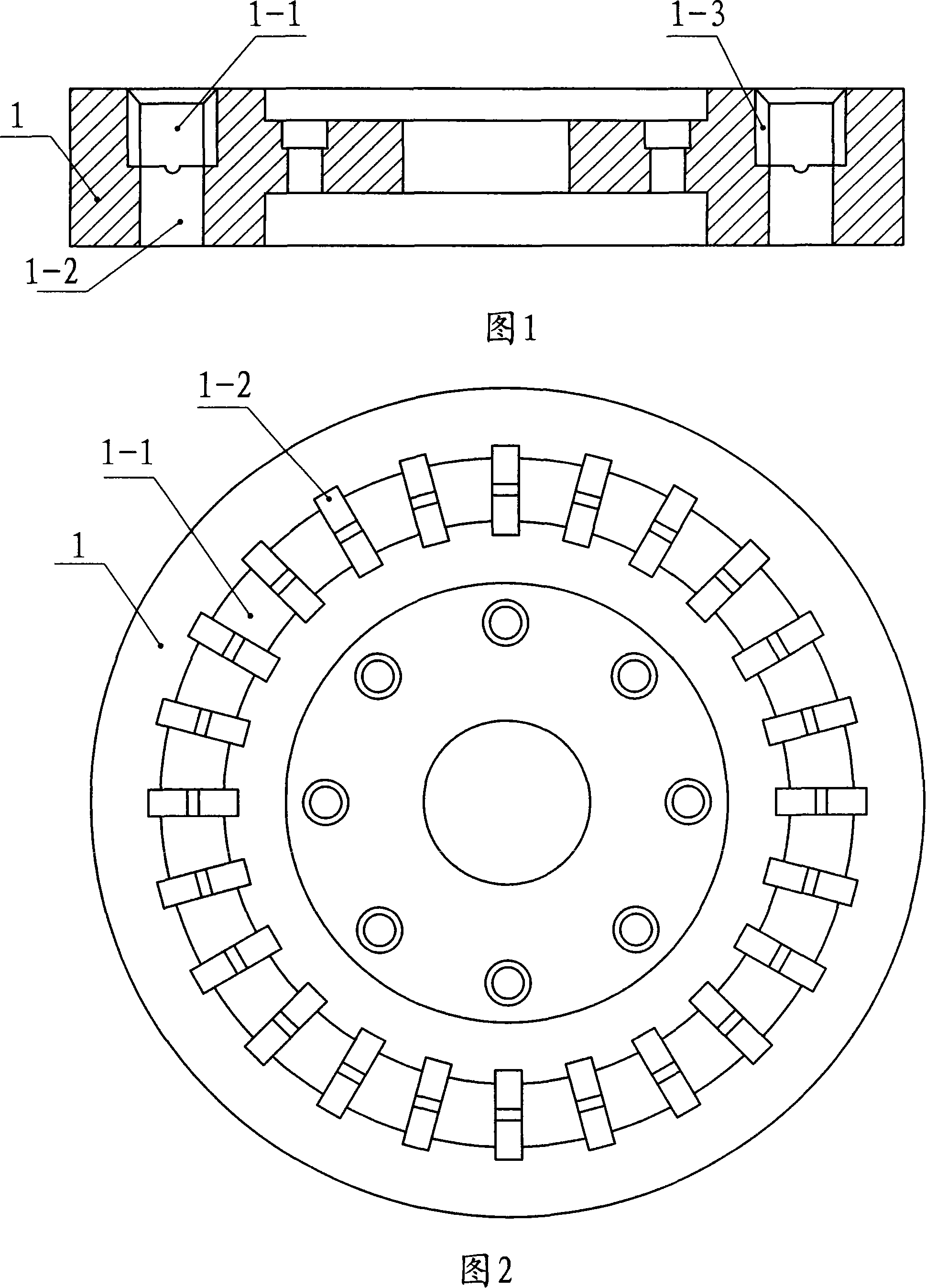
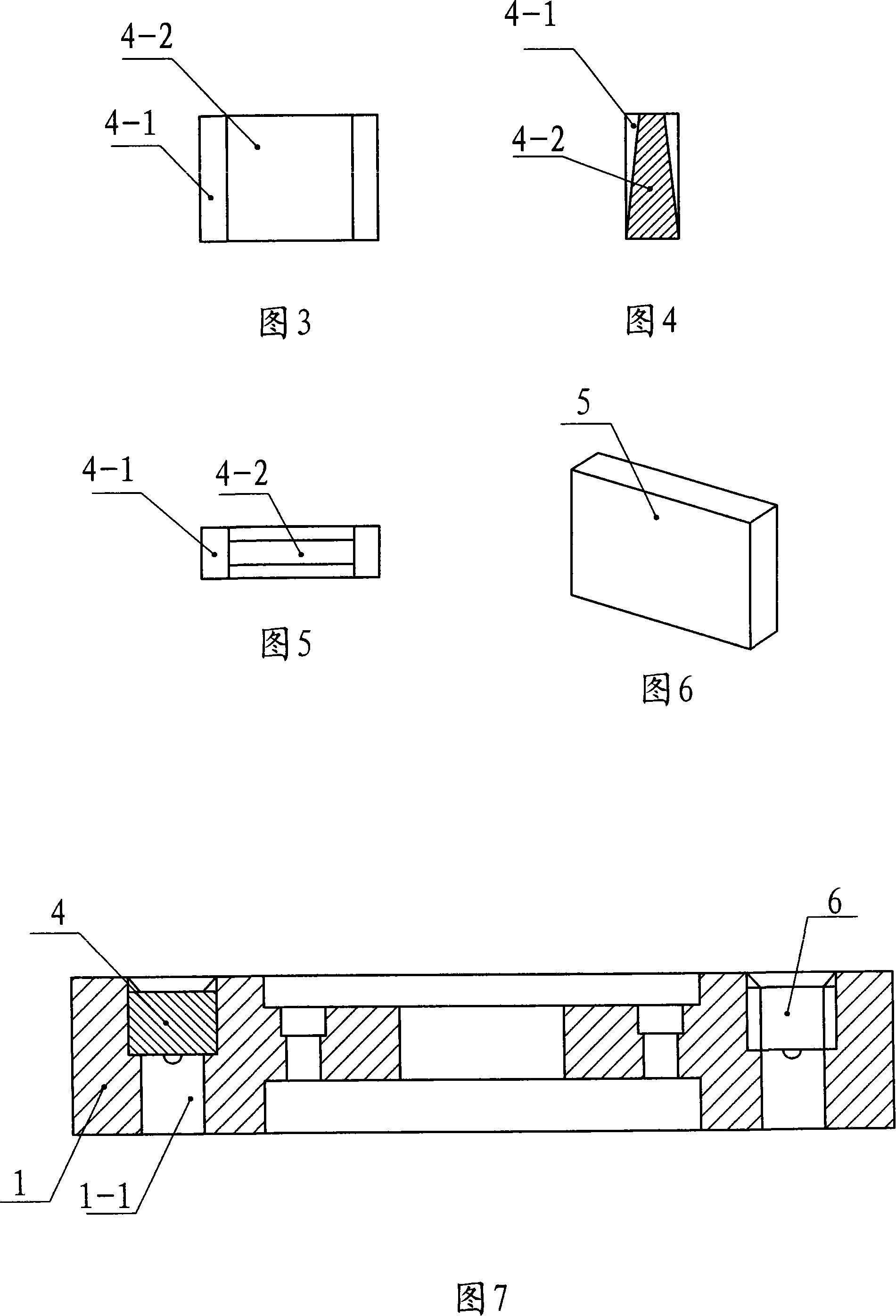
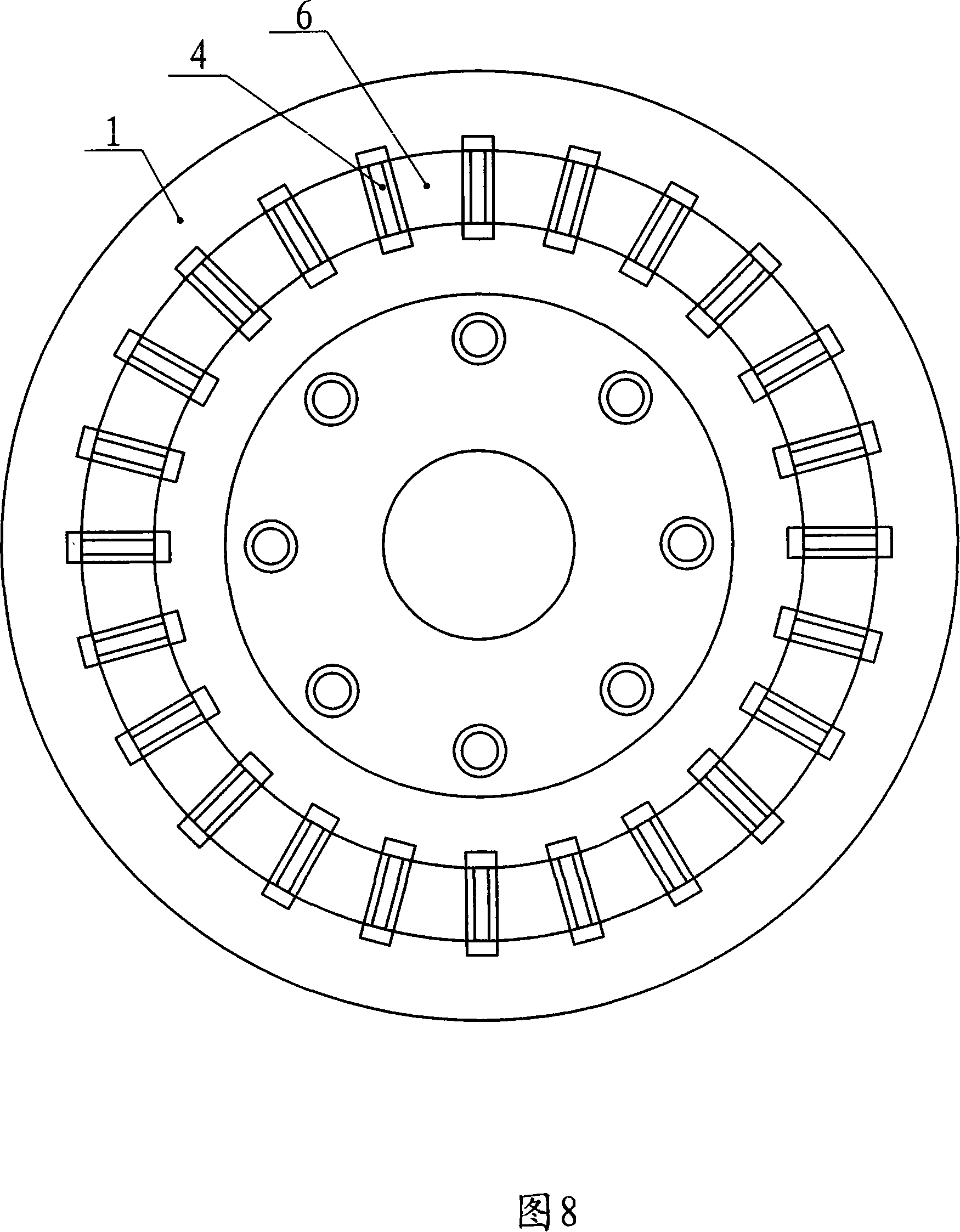
[0043] Embodiment 1: Referring to Fig. 1, Fig. 2, Fig. 3, Fig. 4, Fig. 5, Fig. 7 and Fig. 8, an extruded template assembly in the figure contains a template body 1, and the template body 1 is an annular plate, There is a through hole in the middle, and a fastener connection hole is provided near the through hole. On the template body 1, there is an annular track groove 1-1 concentric with the template body 1 and having a certain depth. The bottom of the track groove 1-1 is evenly distributed along the circumferential direction with a discharge port 1-2 that runs through the template body 1. -2 are provided with a pair of bayonet sockets 1-3, and a detachable module 4 is installed in each pair of bayonet sockets 1-3; adjacent detachable modules 4 and the two side walls of the track groove 1-1 A cavity 6 is formed between them.
[0044] There is one annular track groove 1-1 on the template body 1 .
[0045] The two ends of the detachable module 4 are cuboid clamping parts 4-1,...
Embodiment 2
[0046] Embodiment 2: Referring to FIG. 6, Embodiment 2 is basically the same as Embodiment 1, and the similarities will not be repeated. The difference is that the detachable module 4 described in Embodiment 2 is a cuboid, and the adjacent modules 4 A mold cavity 6 with the same upper and lower thickness is formed between the side wall and the side wall of the track groove 1-1; that is, the module 4 in the first embodiment is replaced by the module 5.
Embodiment 3
[0047] Embodiment 3: Referring to Fig. 9 and Fig. 10, Embodiment 3 is basically the same as Embodiment 1, and the similarities will not be repeated. The difference is the annular track groove 1-1 on the template body 1 described in Embodiment 3 for two.
PUM
 Abstract
Description
Claims
Application Information