Magnetism driven telescopic driver

A magnetostrictive and magnetostrictive rod technology, which is used in the field of devices that convert electrical energy into sound energy and magnetostrictive drives, which can solve the problems of poor synchronization of parallel operation of vibration exciters, limited acoustic wave propagation distance, and difficulty in realizing automatic control, etc. problem, to achieve the effect of non-directional sound, improved sensitivity and fidelity, and compact structure

Inactive Publication Date: 2008-05-28
邸怀玉
View PDF2 Cites 33 Cited by
  • Summary
  • Abstract
  • Description
  • Claims
  • Application Information

AI Technical Summary

Problems solved by technology

[0002] At present, most of the existing loudspeakers are realized in the form of electromagnetic energy conversion. The main working principle is to use the voice coil to drive the vibrating basin to do mechanical movement to radiate sound outward. Because of its structure and vibration mode, it must have problems that cannot be completely solved. Sound deficiencies, such as phase distortion, directivity, sharp sound, voice coil vibration lag, poor fidelity, low sensitivity, etc.
In addition, there is another NXT flat-panel drive technology, which uses an electromagnetic driver combined with a special honeycomb flat panel to reproduce sound in the form of bending vibration on the flat surface, because it still uses a general-purpose electromagnetic conversion structure (moving coil type) Do audio signal conversion form, so there are still disadvantages of traditional speakers
[0003] Chinese patent CN1053091A discloses a method for vibrating parts and the equipment used therein. This kind of vibration can achieve low vibration frequency, poor stability, poor synchronization of a group

Method used


Image

  • Magnetism driven telescopic driver

Examples


Embodiment Construction

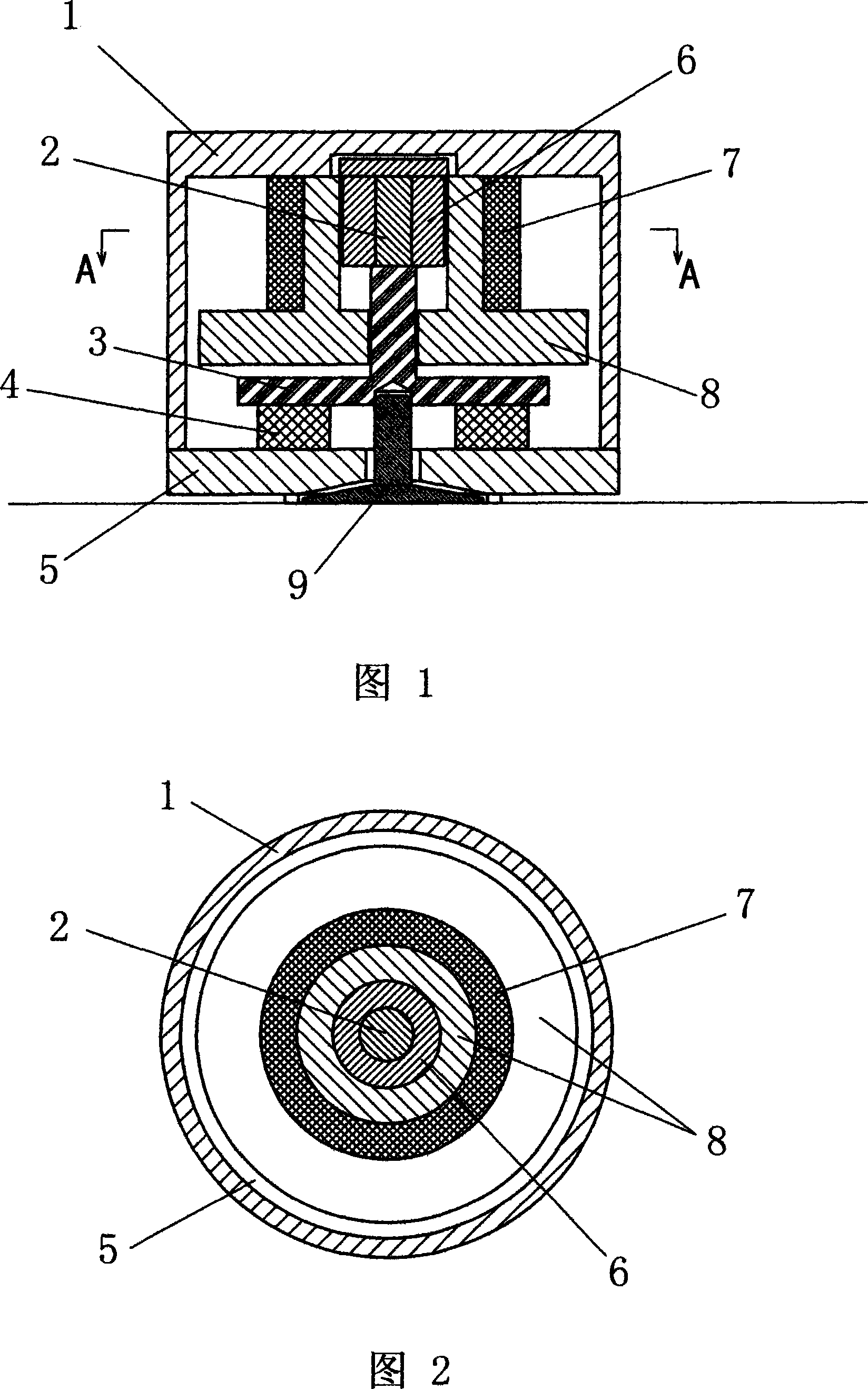
[0019] Referring to Fig. 1 and Fig. 2, it includes a hollow cylindrical shell formed by connecting the upper cover 1 and the base 5, and the shell is made of metal material with good heat dissipation performance. A magnetostrictive rod 2, a fixed support 6, a coil support 8, a drive coil 7, a transmission rod 3 and an output device 9 are respectively arranged along the axis in the housing, and the above-mentioned parts are coaxially arranged. By applying a changing magnetic field, the magnetostrictive rod 2 can expand and contract in the axial direction; the fixed bracket 6 is located on the periphery of the magnetostrictive rod 2 and is made of a magnetically permeable material for providing a bias magnetic field to the magnetostrictive rod 2 Magnetic conduction and positioning; the fixed bracket 6 is cylindrical with one end closed and the other open, and the magnetostrictive rod 2 is a cylinder, which is accommodated in the hollow portion of the cylindrical fixed bracket 6 ....


PUM


Abstract

The invention discloses a manetostrictor driver, comprising a shell body, a manetostrictor rod, a coil brace and a drive coil; wherein, a transmission rod is arranged along the stretching direction of the manetostrictor rod, one end of the transmission rod contacts with the manetostrictor rod, and the other end contacts with a follower extending out of the shell body; a flexible component is arranged between the transmission rod and the shell body; part or all of the coil brace which is made of magnetic material offers bias magnetic field to the manetostrictor rod. The invention combines a permanent magnet providing the bias magnetic field and the coil brace into a whole, the structure is compacter, and the volume of the driver is diminished, thereby being beneficial to heat output; in addition, the manetostrictor rod is driven by adopting the most simplified way of magnetic drive, thereby reducing the magnetic drag of a magnetic circuit to ensure that the stretching transformation of the manetostrictor rod is more delicate, the voice has no hysteresis quality, and the fidelity is high. In addition, because the direct output is adopted, the problems of phase change and distortion can be reduced, and the structure is further simplified and optimized.

Description

technical field [0001] The invention belongs to the field of multistage energy conversion and audio technology, and relates to a device for converting electric energy into sound energy, in particular to a magnetostrictive driver. Background technique [0002] At present, most of the existing loudspeakers are realized in the form of electromagnetic energy conversion. The main working principle is to use the voice coil to drive the vibrating basin to do mechanical movement to radiate sound outward. Because of its structure and vibration mode, it must have problems that cannot be completely solved. Sound deficiencies, such as phase distortion, directivity, sharp sound, voice coil vibration lag, poor fidelity, low sensitivity and other shortcomings. In addition, there is another NXT flat-panel drive technology, which uses an electromagnetic driver combined with a special honeycomb flat panel to reproduce sound in the form of bending vibration on the flat surface, because it stil...

Claims


Application Information

Patent Timeline
IPC IPC(8): H04R15/00
Inventor 邸怀玉
Owner 邸怀玉
Why Eureka
Try Eureka