Heat radiator

A heat sink and heat sink technology, which is applied in cooling/ventilation/heating transformation, instruments, electrical digital data processing, etc., can solve the problems of heat transfer capacity reduction of heat pipes, capillary structure damage, and affecting the overall heat dissipation performance of heat sinks, etc., to achieve High heat dissipation performance, the effect of overcoming the interface thermal resistance

Inactive Publication Date: 2008-05-28
FU ZHUN PRECISION IND SHENZHEN +1
View PDF0 Cites 5 Cited by
  • Summary
  • Abstract
  • Description
  • Claims
  • Application Information

AI Technical Summary

Problems solved by technology

However, when the heat pipe is bent, there is a certain damage to the capillary structure in the shell, and the heat transfer capacity of the heat pipe is reduced to a certain extent every time it is bent, and there is an interface thermal resistance between the heat pipe and the radiator due to the combination, which also affects the heat dissipation device. overall cooling performance

Method used


Image

  • Heat radiator
  • Heat radiator
  • Heat radiator

Examples


Embodiment Construction

[0012] The heat dissipation device of the present invention will be further described below with reference to the accompanying drawings.

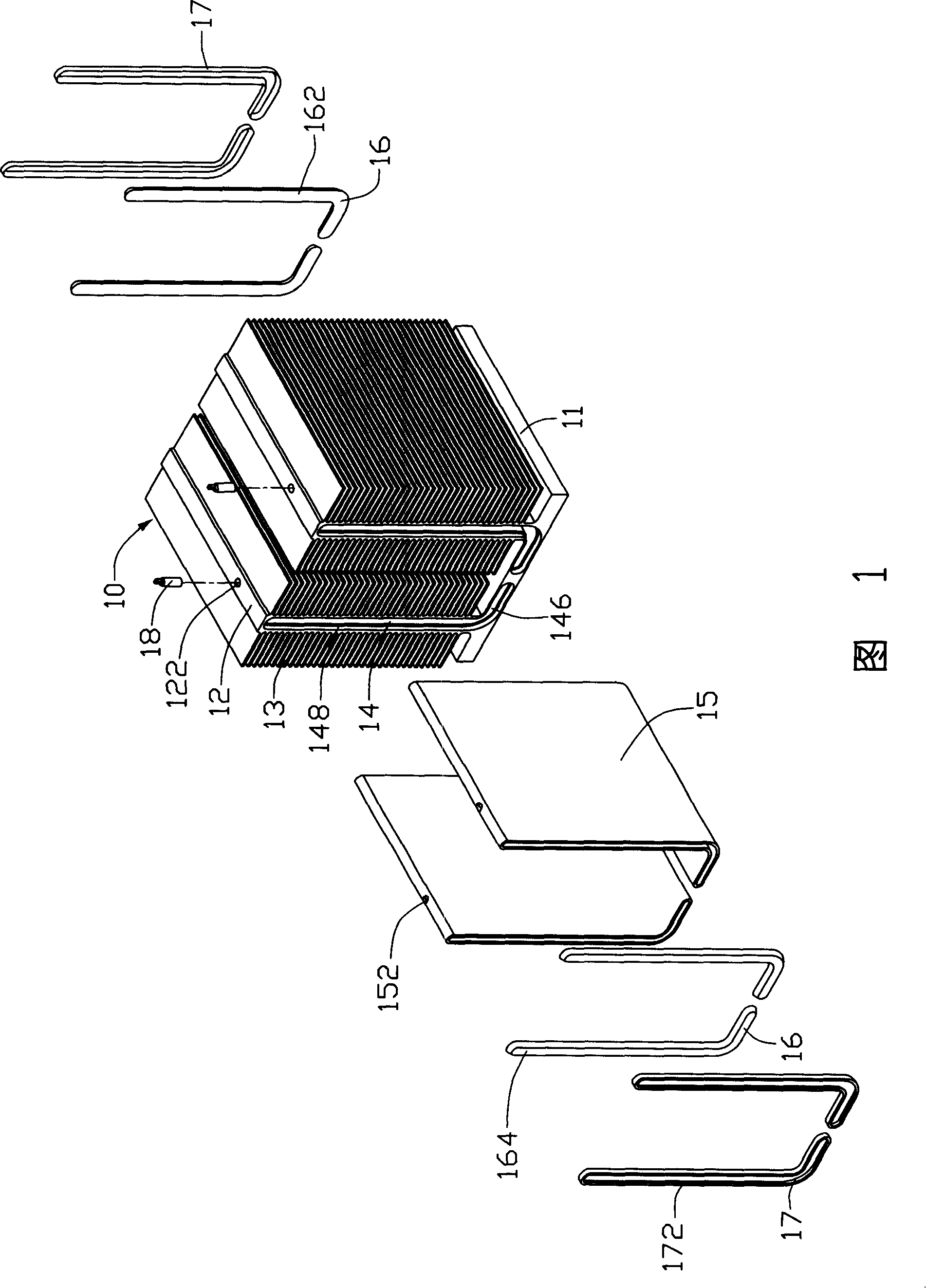
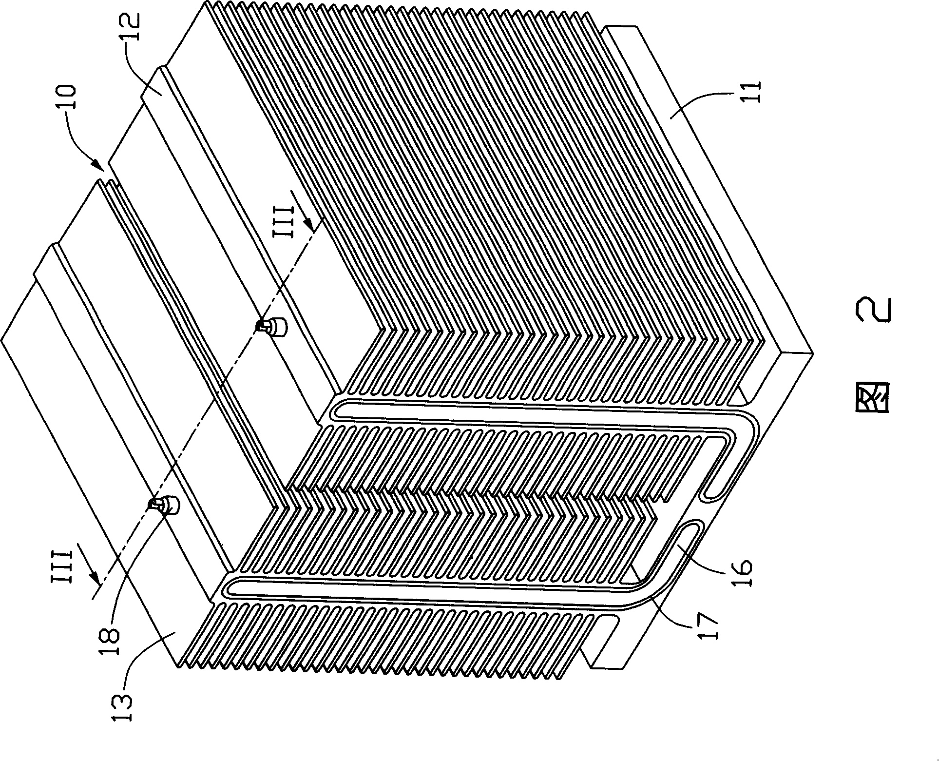
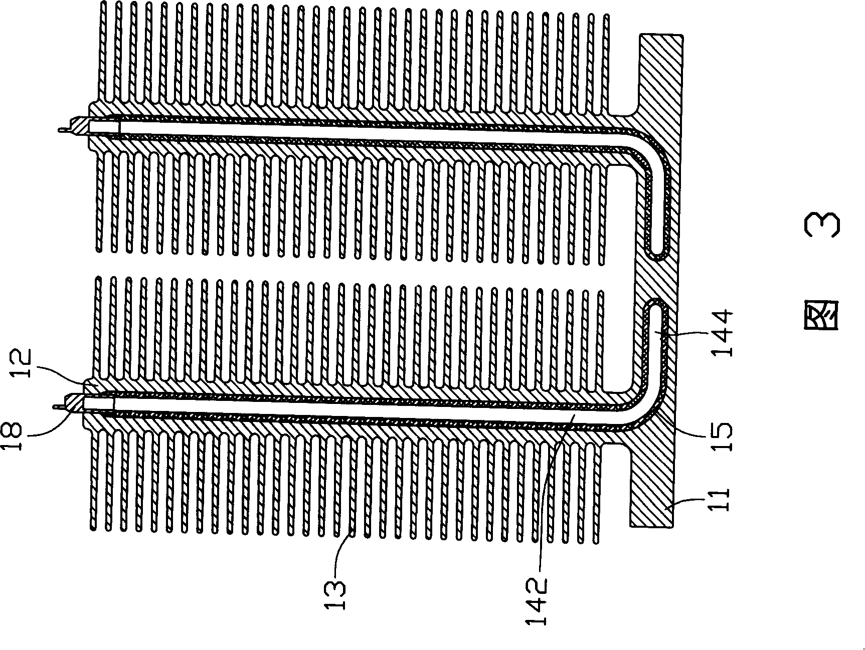
[0013] Please refer to Fig. 1 to Fig. 3, the heat dissipating device of the first embodiment of the present invention comprises the heat sink 10 of extruded aluminum, and this heat sink 10 comprises a rectangular heat conduction base 11, and the bottom surface of this heat conduction base 11 forms a plane (not marked) for The electronic components are bonded, and the middle part of the top surface of the heat conduction base 11 has two heat conduction wings 12 vertically extending upward at a certain distance. The heat conduction wings 12 are plate-shaped with a certain thickness, and a plurality of parallel and spaced cooling fins 13 are vertically extended laterally on two sides thereof. Each heat conduction wing 12 is provided with a channel 14 with a slightly L-shaped cross section in the heat conduction base 11 connected thereto. The ...


PUM


Abstract

The invention discloses a heat abstractor for cooling a heating electronic component, and the heat abstractor comprises a heat conducting base seat processed and moulded by an integer, at least two heat conducting wing parts extending out of the heat conducting base seat at intervals, and a plurality of radiation fins which are arranged at intervals and extended out of the surface of the heat conducting wing parts. Communicated conduits are arranged in the heat conducting base seat and the heat conducting wing parts, and a right amount of working liquid is sealed in the conduits. Compared with the prior art, the conduits and the heat abstractor form an unassembled interface, which overcomes the unfavorable influences of the bending of the traditional heat tube and the interface heat resistance brought by the joint of the radiation fins.

Description

technical field [0001] The invention relates to a heat dissipation device, in particular to a heat dissipation device for electronic components. Background technique [0002] Electronic components such as the central processing unit (CPU) generate a large amount of heat energy when they are running. Especially with the continuous improvement of the processing capacity of electronic components and the smaller size, the unit calorific value is getting larger and larger. For this reason, the industry has adopted heat pipes as The components of the radiator, the heat transfer speed of the heat pipe is fast and the distance is long, and the heat conduction of each part of the radiator is connected through the heat pipe, which can quickly and evenly spread the heat of the electronic components to all parts of the radiator and quickly dissipate the heat outward, so The performance of the radiator is effectively improved. [0003] Generally, a heat pipe is provided with a capillary...

Claims


Application Information

Patent Timeline
Patent Type & Authority Applications(China)
IPC IPC(8): H05K7/20H01L23/367G06F1/20
Inventor 李冬云利民马无疆
Owner FU ZHUN PRECISION IND SHENZHEN
Why Eureka
Try Eureka