Timepiece component and timepiece having the timepiece component

A clock and component technology, applied in the field of clock components, can solve the problems of decreased oil retention, difficulty in realizing non-refueling clock components, oil splashing, flow and the like

Inactive Publication Date: 2008-06-04
SEIKO EPSON CORP +1
View PDF1 Cites 12 Cited by
  • Summary
  • Abstract
  • Description
  • Claims
  • Application Information

AI Technical Summary

Problems solved by technology

That is, it is difficult to realize a timepiece part without refueling
[0016] In addition, when refueling is performed in reality, in order to retain the oil dedicated to watches, for example, by covering the frictional sliding part and the switching part with fluorine-based polyester, etc., the oil retention property is improved, and oil splashing and flow are

Method used


Image

  • Timepiece component and timepiece having the timepiece component
  • Timepiece component and timepiece having the timepiece component
  • Timepiece component and timepiece having the timepiece component

Examples


no. 1 approach

[0057] (The overall structure of electronically controlled mechanical clocks)

[0058] The first embodiment of the present invention will be described below based on the drawings.

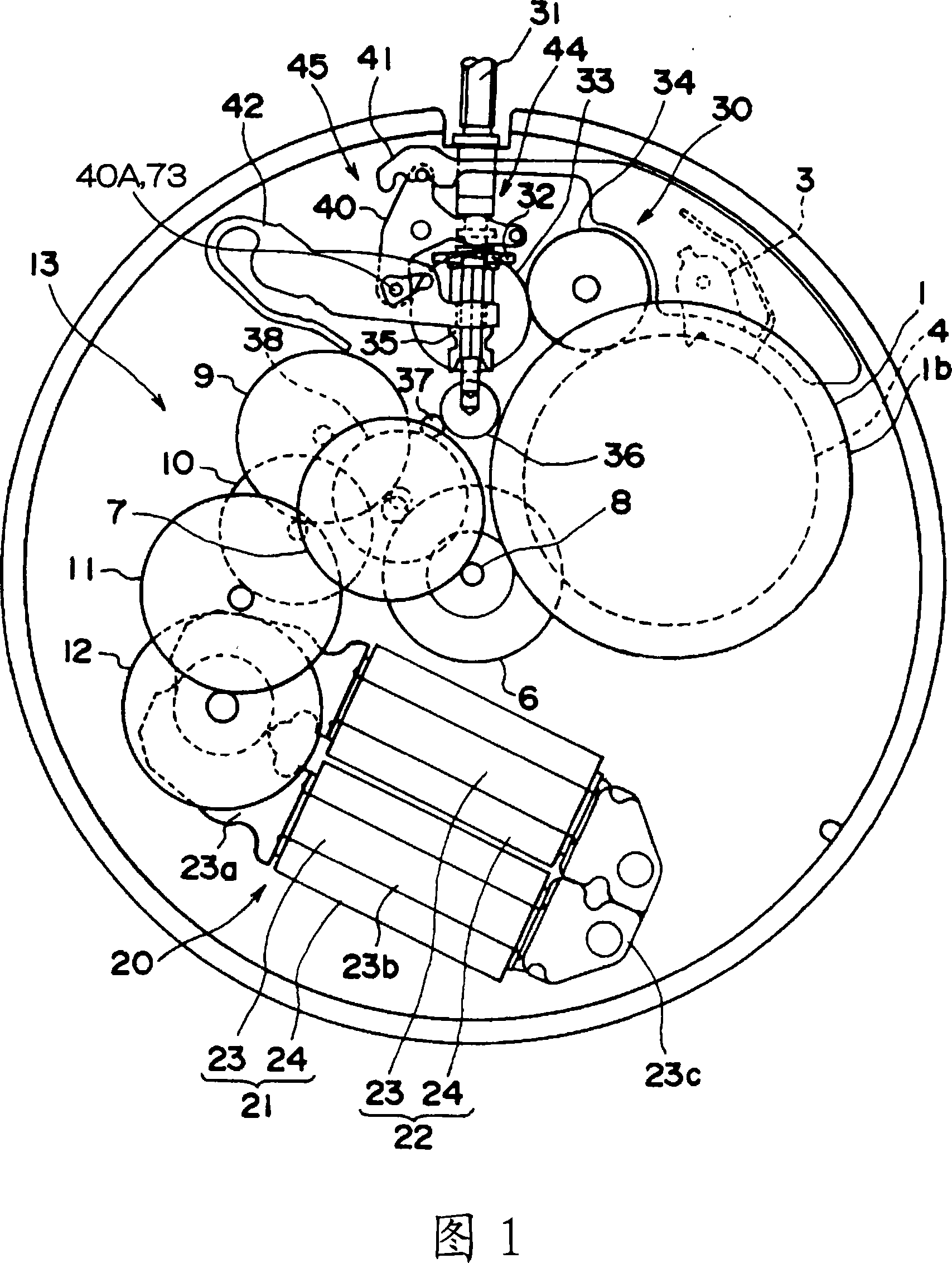
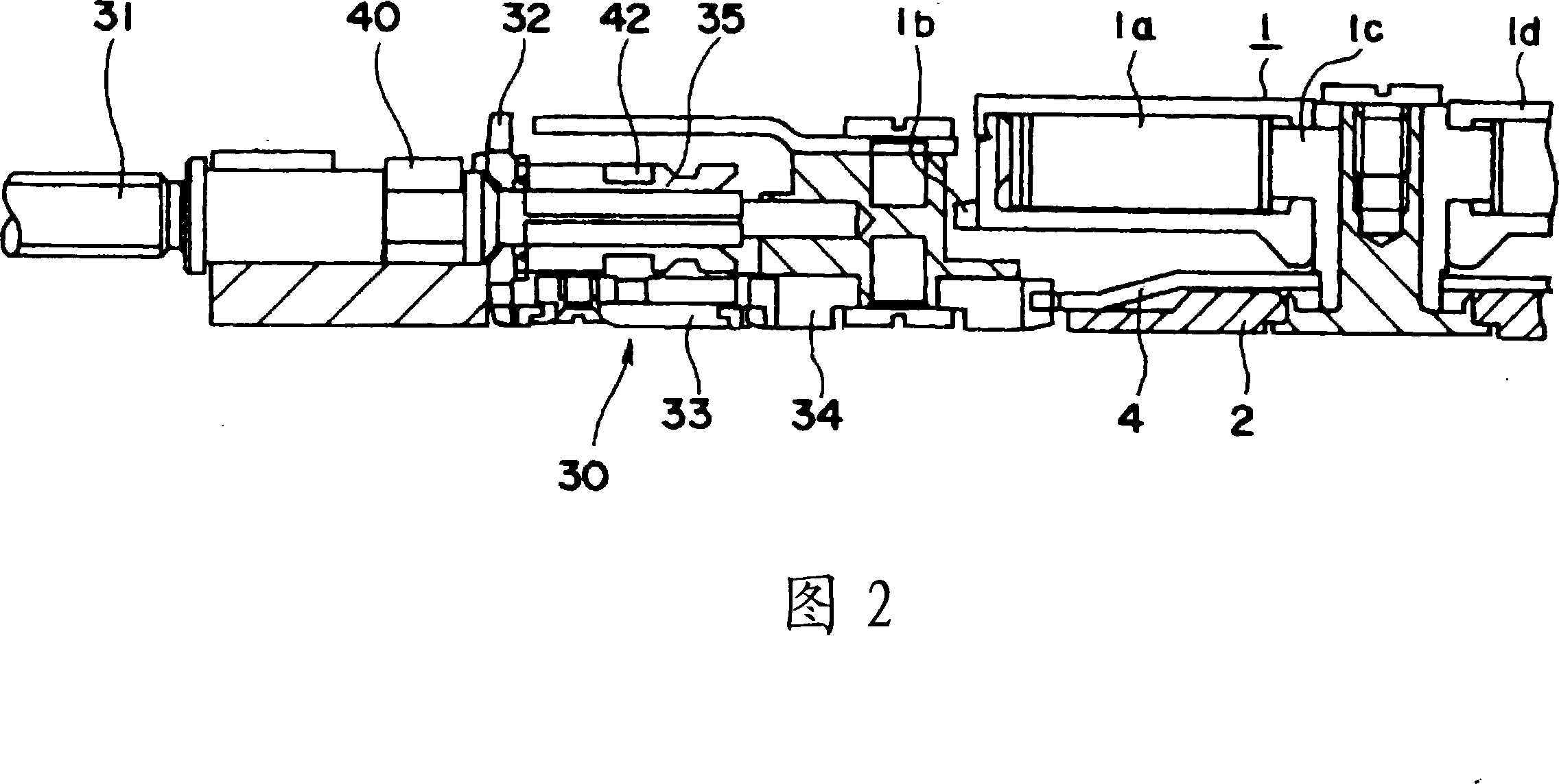
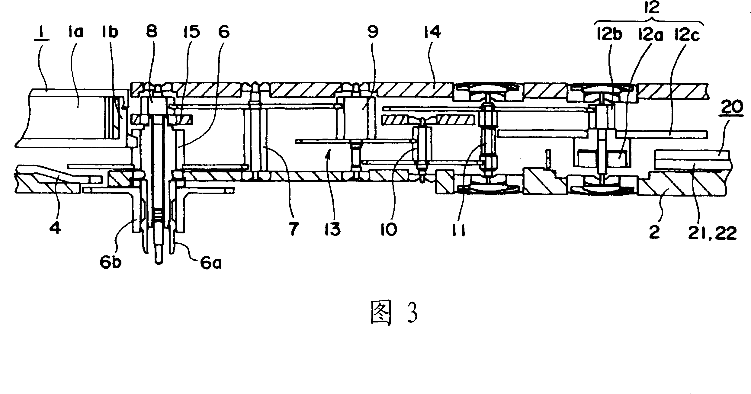
[0059] Fig. 1 is a plan view of the outline of the electronically controlled mechanical timepiece of the present embodiment, and Figs. 2 to 3 are cross-sectional views of main parts thereof.

[0060] In Figures 1 to 3, the electronically controlled mechanical timepiece has a barrel wheel 1, which is composed of a barrel 1a, a barrel gear 1b, a barrel spindle 1c, and a barrel cover 1d . The outer end of the mainspring 1a is fixed on the barrel gear 1b, and the inner end is fixed on the barrel spindle 1c. The barrel spindle 1c is supported on the main board 2 and rotates integrally with the ratchet wheel 4.

[0061] The ratchet wheel 4 is engaged with the shift gear 3 so as to rotate in a clockwise direction but not in a counterclockwise direction. The ratchet wheel 4 is configured to rotate the vertical...

no. 2 approach

[0100] Next, the second embodiment of the present invention will be described. In this embodiment, as shown in FIG. 8, the oil 76 dedicated for timepieces is sandwiched between the third pinion 71 and the lower pivot 72 and the pivot hole 51. Except for the point of refueling in this way, the structure of the timepiece of this embodiment is the same as that of the timepiece of the first embodiment.

[0101] FIG. 9 is an enlarged view showing the surfaces of the No. 3 pinion gear 71 and the lower pivot 72 covered by the composite plating layer 73.

[0102] As shown in FIG. 9, the oil 76 dedicated for timepieces is held by the carbon nanotubes 75A forming the carbon nanotube layer 75. At this time, since the carbon nanotube layer 75 is formed non-directionally, the oil is not easy to flow in any direction and can have uniform oil retention.

[0103] In this embodiment, as in the first embodiment, the surfaces of the third pinion gear 71 and the lower pivot 72, that is, the contact s...


PUM

PropertyMeasurementUnit
Film thicknessaaaaaaaaaa
Surface roughnessaaaaaaaaaa
Thicknessaaaaaaaaaa

Abstract

The invention provides a timepiece component and a timepiece comprising same. The abrasion resistance, lubrication and oiliness of a frictional sliding region and a switch region of the timepiece can be improved remarkably, and the timepiece can be used for a long time. The pivot shaft part above and under No.3 gear (7) of the electronic control mechanical timepiece is born by a jewelled bearing (50) assembled on a train bar and a mainboard (2). The No.3 gear comprises a No.3 pinion and a lower pivot shaft (72) disposed at the lower part of the No.3 gear. The jewelled bearing is composed of a carbuncle with a pivot shaft hole formed in the center. The No.3 pinion and the surface of the lower pivot shaft are covered with a composite plate (73) which comprises: a nickel coating layer (74) formed by electroplating treatment; and a carbon nano tube layer (75) formed astatically by using dispersion agent such as polyacrylic acid. Thereby, the No.3 pinion and the lower pivot shaft slide in the pivot shaft hole with an interlayer of carbon nano tube layer.

Description

Technical field [0001] The present invention relates to a timepiece component and a timepiece having the timepiece component. Background technique [0002] In recent years, there has been known a composite plating layer in which insoluble particles are mixed in an ordinary electroplating bath or an electroless plating bath to eutectify with the metal, and the particles are mixed in the metal plating layer. In the composite plating layer, by selecting the metal plating layer and particles, it is possible to cover the plating layer with excellent hardness, abrasion resistance, lubricity, etc. (for example, refer to Patent Document 1). [0003] In the composite plating described in Patent Document 1, by mixing a brightener, polyacrylic acid, and carbon nanotubes in a Watts cell containing nickel sulfate and nickel chloride as the main components, the composite plating solution is adjusted and the plating treatment is performed. This can be coated with a nickel plating layer as a met...

Claims


Application Information

Patent Timeline
IPC IPC(8): G04B31/08
CPCC25D7/005C25D15/00
Inventor 藤森章浩村井正己新井进
Owner SEIKO EPSON CORP
Why Eureka
Try Eureka