Process for battery powdery ring inverted insertion into steel case and its device for entering ring

A battery steel shell and powder ring technology, which is applied in the manufacturing of primary batteries, secondary batteries, circuits, etc., can solve the problems of powder residue, short circuit, and alkali creeping, so as to improve storage life, ensure electrical safety, and prevent alkali creeping. Effect

Inactive Publication Date: 2008-06-04
潮州正龙电池工业有限公司
View PDF0 Cites 21 Cited by
  • Summary
  • Abstract
  • Description
  • Claims
  • Application Information

AI Technical Summary

Problems solved by technology

One of the main reasons for the so-called "alkali creep, short circuit, and liquid leakage" during the use of the battery is that the positive electrode alkali manganese powder r

Method used


Image

  • Process for battery powdery ring inverted insertion into steel case and its device for entering ring
  • Process for battery powdery ring inverted insertion into steel case and its device for entering ring

Examples


Embodiment 1

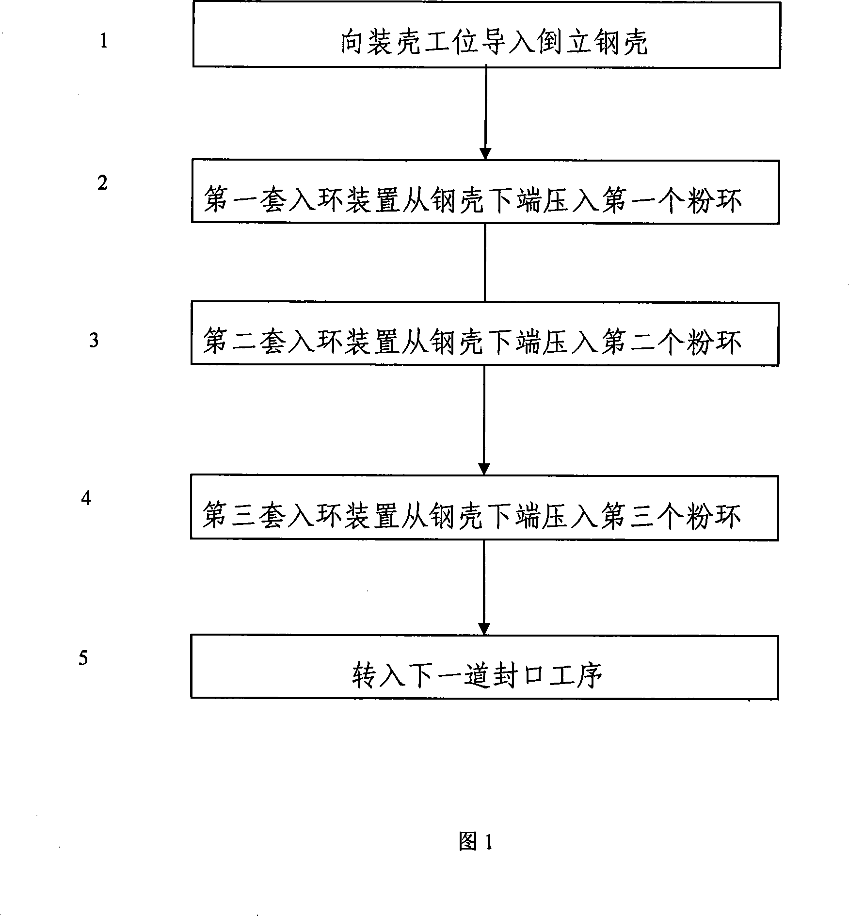
[0019] Embodiment 1 is shown in Figures 1-4: a process of inserting battery powder rings upside down into steel shells, which is carried out on the ring-entry devices arranged adjacently in the complete set of automatic battery production equipment, according to the following steps:

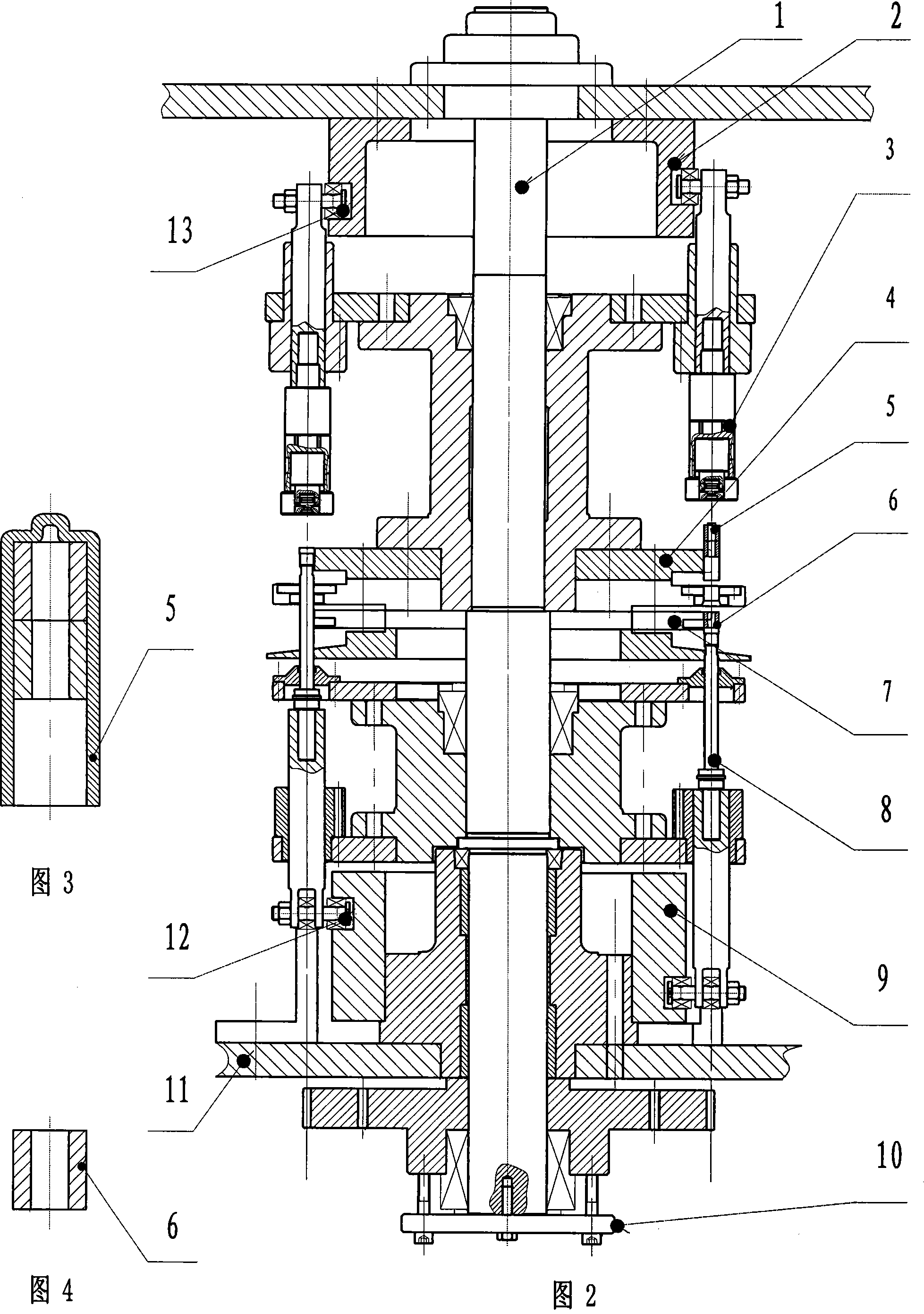
[0020] ①Introduce the inverted battery steel case 5 to the case loading station of the continuously rotating upper case feeding turntable 4;

[0021] ② The inverted battery steel case 5 and the alkali manganese powder ring 6 are transferred to the first ring-entry station synchronously by the upper shell feeding turntable 4 and the lower feeding ring turntable 7 respectively, and the lower inserting ring component assembly 8 moves the first ring from bottom to top. An alkali manganese powder ring 6 is pressed into the inverted steel shell 5;

[0022] ③The battery steel case 5 is transferred to the shell ejection station, the upper cylinder guide cam 2 lifts up the insertion rod of the steel case ...

Embodiment 2

[0025] Embodiment 2 is shown in Figure 2-4: a ring-entry device used for the process of inserting the battery powder ring upside down into the steel shell. The two ends of its transmission vertical shaft 1 are installed on the frame 11 through bearings and bearing sleeves. 10 is installed on the lower end of the transmission vertical shaft 1 relying on two conical semi-circular tiles; the steel shell insert part assembly 3, the upper feed shell turntable 4, the lower feed ring turntable 7, and the lower insert ring part assembly 8 pass through the two cones in turn. Shaped semicircle tile tightly fits and is installed in the middle section of transmission vertical shaft 1. The upper cylinder guide cam 2 and the lower cylinder guide cam 9 are concentric with the vertical shaft 1 and are not connected, and the upper cylinder guide cam 2 and the lower cylinder guide cam 9 are fixedly installed on the frame 11 . The roller 13 of the steel shell insertion part assembly 3 is embedde...


PUM


Abstract

The invention relates to a technique for reversely inserting a battery powder ring into a steel shell and ring entering devices thereof. In the ring entering devices side by side, a first powder ring is pressed into an inverted steel shell according to the inverted battery steel shell and a ring inserting part is imported in the shell assembly work position from bottom to top; the battery steel shell quits from a shell quitting work position; a second and a third powder rings are pressed into a second and a third ring entering devices side by side; the battery steel shell full of ring powder is transferred to the next process of sealing; the processes are carried out in turn. Two sides of a transmission vertical shaft in the ring entering device are installed on a stander through a bearing and a bearing cover; an inserted part assembly of the steel shell, an upper shell feeding turntable, a lower ring feeding turntable, a lower inserted ring part assembly and a transmission gear are fixedly installed on the transmission vertical shaft in turn; an upper cylindrical guiding cam and a lower cylindrical guiding cam are fixed installed on the stander. The invention adopts the technique of pressing ring from bottom to top, prevents the rudimental powder from dropping into the inner side of the battery steel shell, avoids weak points like alkaline climb, short circuit, liquid leaking and prolongs the storage life of the battery largely.

Description

technical field [0001] The invention relates to a battery powder ring loading process and its equipment, in particular to a battery powder ring insertion process upside down into a steel case and a ring-entry device. Background technique [0002] With the continuous improvement of people's living standards, the demand for batteries in all walks of life is increasing, and it is developing in the direction of large capacity, long life, safety, and pollution-free. To meet the ever-increasing social needs, continuous improvement of technology is an urgent issue. One of the main reasons for the so-called "alkali creep, short circuit, and liquid leakage" during the use of the battery is that the positive electrode alkali manganese powder ring is pressed into the steel shell of the battery using the traditional powder ring from top to bottom. The mouth is vertically upward, causing the powder to remain inside the steel shell. Contents of the invention [0003] The technical pro...

Claims


Application Information

Patent Timeline
IPC IPC(8): H01M10/04H01M6/00
CPCY02E60/12Y02E60/10Y02P70/50
Inventor 黄培龙曾广英池镇定许崇源陈镜波张文华
Owner 潮州正龙电池工业有限公司
Why Eureka
Try Eureka