Ultrasonic sensor

A sensor and ultrasonic technology, applied in the field of coupling layer, can solve the problems of uneven distribution of bubble diameters in coupling parts, low production efficiency of coupling parts, limited part of coupling parts, etc., and achieve the effect of improving production stability, improving productivity and a certain speed of sound

Inactive Publication Date: 2008-06-11
PANASONIC CORP
View PDF2 Cites 4 Cited by
  • Summary
  • Abstract
  • Description
  • Claims
  • Application Information

AI Technical Summary

Problems solved by technology

[0007] However, in this conventional manufacturing method, only the second resin layer used for the coupling member is formed because the first resin layer in which the resin adheres to the periphery of the glass microspheres and the second resin layer in which the main component is only a resin with a relatively high specific gravity are formed. One resin layer, the remaining second resin layer is discarded, so the part that can be taken from the manufactured coupling part is limited, so the production efficiency of the coupling part is less manufacturing method
[0008] In addition, in order to form bubbles with a stable bubble diameter in inorganic materials, bubbles are introduced into the slurr

Method used


Image

  • Ultrasonic sensor
  • Ultrasonic sensor
  • Ultrasonic sensor

Examples


no. 1 approach

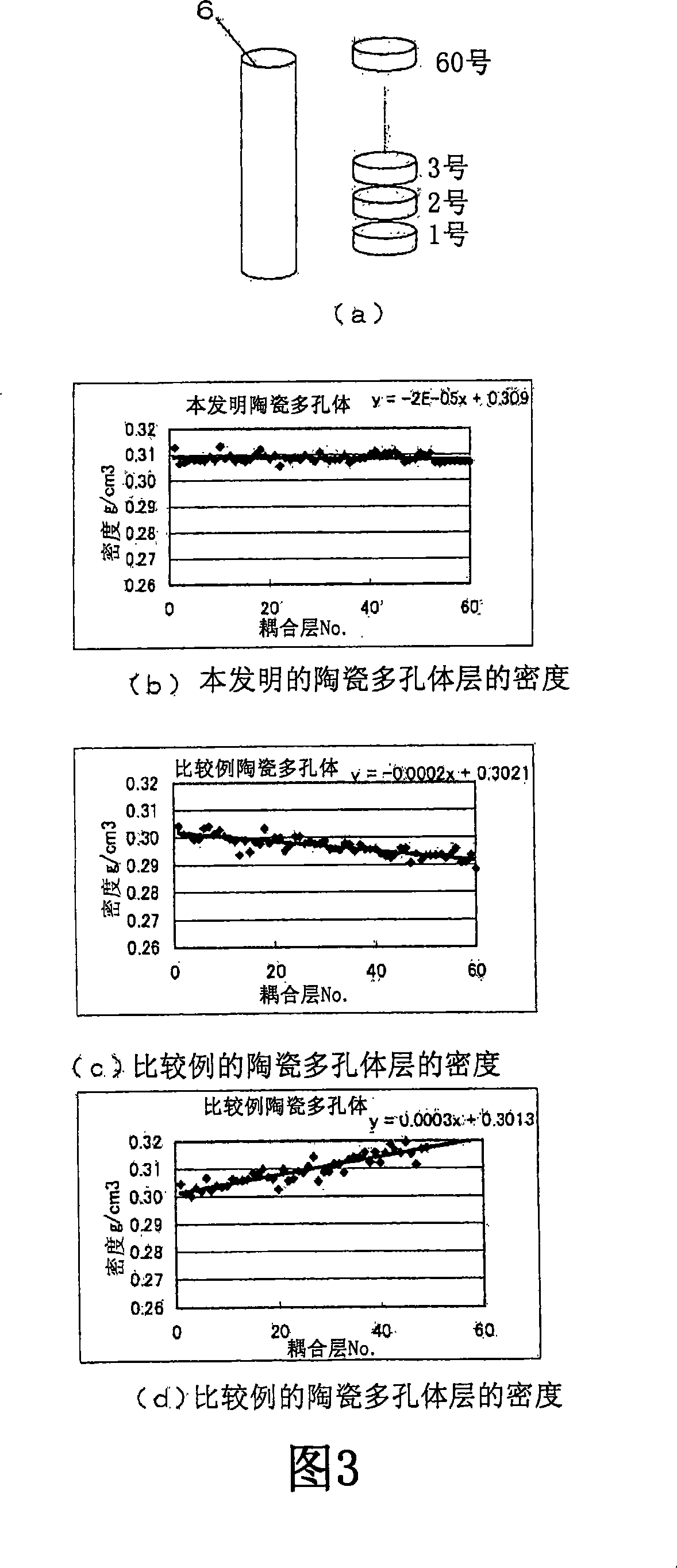
[0032] FIG. 1 shows the flow of the manufacturing method of the coupling member and the coupling layer in the first embodiment of the present invention in a schematic process diagram.

[0033] Inside the container 1 shown in FIG. 1 there is a storage chamber 2 with a predetermined volume. In the above-mentioned storage chamber 2, a slurry 3 containing a hollow spherical resin is stored. The slurry 3 is mixed with oxide ceramics such as silicon carbide. Inorganic material, water or organic solvent, and gelling agent are used to make a slurry, and hollow spheres (particles) of resin containing liquefied gas are contained in the slurry. The hollow spherical resin-containing slurry 3 injected into the container 1 is shaped into the shape of the container 2, and after the heating step, the slurry is oxidized and fired to obtain a ceramic porous body.

[0034] The manufacturing method of the hollow sphere resin-containing slurry of the present invention is: mixing inorganic material...

no. 2 approach

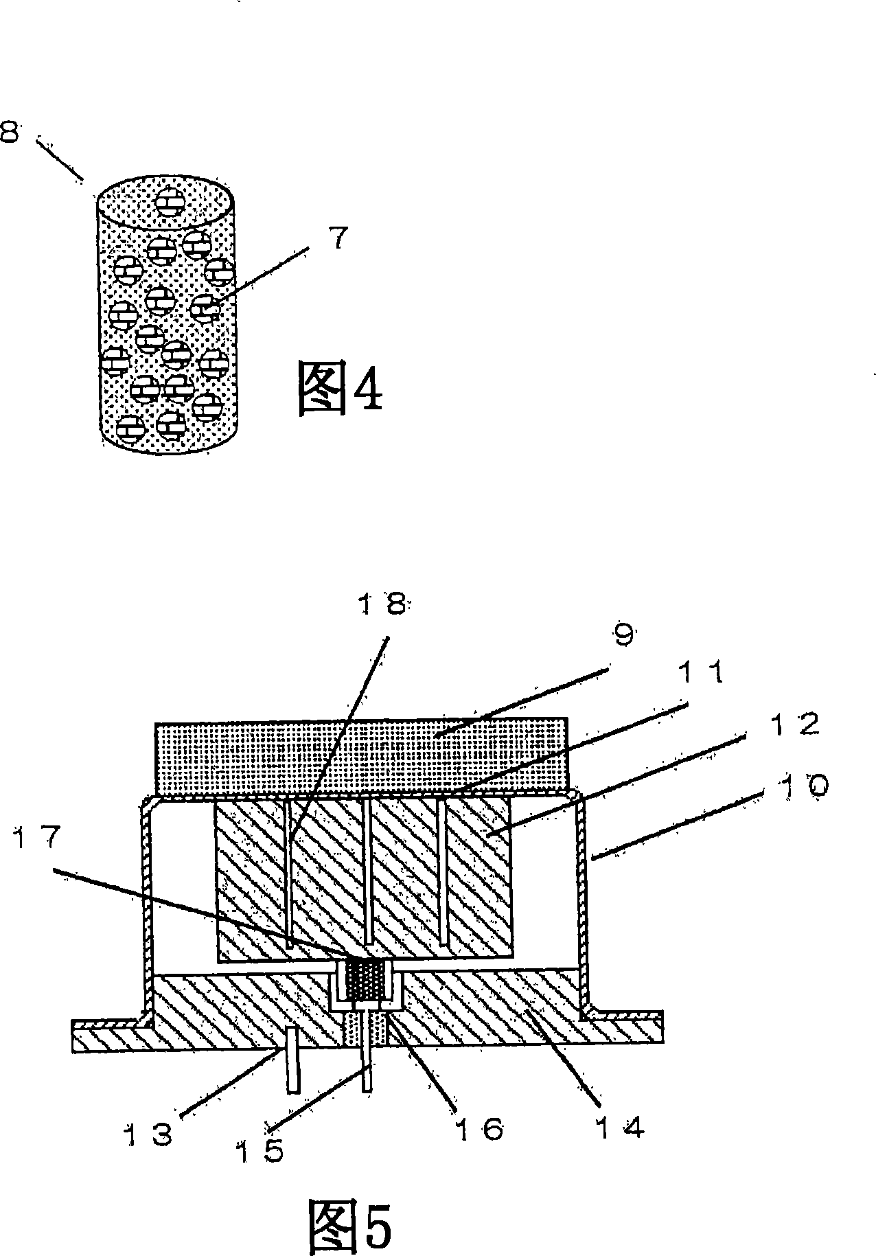
[0049] FIG. 5 is a cross-sectional view of an ultrasonic sensor using the coupling layer 9 obtained in the above embodiment.

[0050] A cylindrical case 10 made of a conductive material has a top 11, a piezoelectric body 12 is bonded to an inner wall surface of the top 11, and a coupling layer 9 is bonded to an outer wall surface.

[0051] The lower opening of the cylindrical casing 10 is closed by the terminal plate 14 connected to the terminal 13 on one side, and the terminal 15 on the other side passes through the terminal plate 14 through the electrical insulating material 16, and is connected to the conductor 17, and the conductor 17 is connected to the pressure. The lower surface of the electric body 12 is in contact. A plurality of vertical grooves 18 are formed in the piezoelectric body 12 .

[0052] When a voltage is applied from the terminals 13 and 15 to the piezoelectric body 12 via the conductor 17, the piezoelectric body 12 vibrates due to a piezoelectric phenom...


PUM

PropertyMeasurementUnit
Particle sizeaaaaaaaaaa
The average particle sizeaaaaaaaaaa

Abstract

The object of the present invention is to control the diameter of pores in a coupling layer formed of a ceramic porous body and organic glass. An ultrasonic sensor is provided, comprising a piezoelectric body, a casing for containing the piezoelectric body, and a coupling layer arranged on the top of the casing, wherein the coupling layer is composed of a ceramic porous body with uniform glass spheres in the holes, and the The glass spheres are formed from a dried gel of plexiglass. In the ultrasonic sensor, resin particles (4) containing liquefied gas are added to a slurry (3) using an inorganic material, and the resin particles (4) are foamed in a first heating step to form hollow spherical particles (5) In the second heating step, the ceramic porous body is fired to form plexiglass (7) in the controlled pores, and a coupling layer (9) with stable internal density and constant acoustic impedance is produced, thereby providing a stable output Ultrasonic sensor.

Description

technical field [0001] The invention relates to a coupling layer for improving the acoustic performance of an ultrasonic sensor. Background technique [0002] In the past, the manufacturing method of the coupling layer used in the ultrasonic sensor etc. has the following method: for example, as shown in Figure 6 (a), after mixing microspheres 20 and resin 21 in the container 19, as shown in Figure 6 (b) , together with the container 19 is set in the centrifugal separator 22 to drive it. Then, as shown in Figure 6 (c), in the mixture of glass microspheres 20 and resin 21, use the difference in specific gravity to separate into the first resin layer 21a of glass microspheres with a smaller specific gravity as the main component, and the first resin layer 21a only by comparing the specific gravity. The second resin layer 21b that big resin layer is formed, forms the second resin layer 21b that is only made up of resin layer 21 in the bottom of container 19, forms the first res...

Claims


Application Information

Patent Timeline
IPC IPC(8): G01F1/66G01P5/24
Inventor 伊藤雅彦
Owner PANASONIC CORP
Why Eureka
Try Eureka