Oxide deposition method of shallow groove isolation region

A technology of shallow trench isolation and deposition method, which is applied in the field of oxide deposition in shallow trench isolation, can solve the problems of complex process, increase process steps, reduce stress and erosion of shallow trench isolation sidewall oxide layer, etc. Achieve the effects of enhancing reliability, reducing R&D costs, and enhancing adhesion

Active Publication Date: 2008-06-11
SEMICON MFG INT (SHANGHAI) CORP +1
View PDF2 Cites 13 Cited by
  • Summary
  • Abstract
  • Description
  • Claims
  • Application Information

AI Technical Summary

Problems solved by technology

[0008] Obviously, although this method provides a method to reduce the stress and erosion of the sidewall oxide layer of shallow trench isolation, it still cannot solve the gap filling problem.
At the same time, the simple combination of the method and the above-mentioned technical solution that can solve the gap filling problem, that is, after the high-density plasma chemical vapor deposition of multiple deposition steps, and then perform an on-site steam generation process, theoretically, can provide both guaranteed An STI / film oxide deposition method with high deposition quality and reduced film stress, but it needs to add a separate process step, which complicates the process

Method used


Image

  • Oxide deposition method of shallow groove isolation region
  • Oxide deposition method of shallow groove isolation region
  • Oxide deposition method of shallow groove isolation region

Examples


Embodiment Construction

[0031] Although the invention will be described in more detail below with reference to the accompanying drawings, in which preferred embodiments of the invention are shown, it should be understood that those skilled in the art can modify the invention described herein and still achieve the advantageous effects of the invention. Therefore, the following description should be understood as a broad instruction for those skilled in the art, rather than as a limitation of the present invention.

[0032] In the interest of clarity, not all features of an actual implementation are described. In the following description, well-known functions and constructions are not described in detail since they would obscure the invention with unnecessary detail. It should be appreciated that in the development of any actual embodiment, numerous implementation details must be worked out to achieve the developer's specific goals, such as changing from one embodiment to another in accordance with sy...


PUM

PropertyMeasurementUnit
thicknessaaaaaaaaaa
thicknessaaaaaaaaaa
thicknessaaaaaaaaaa

Abstract

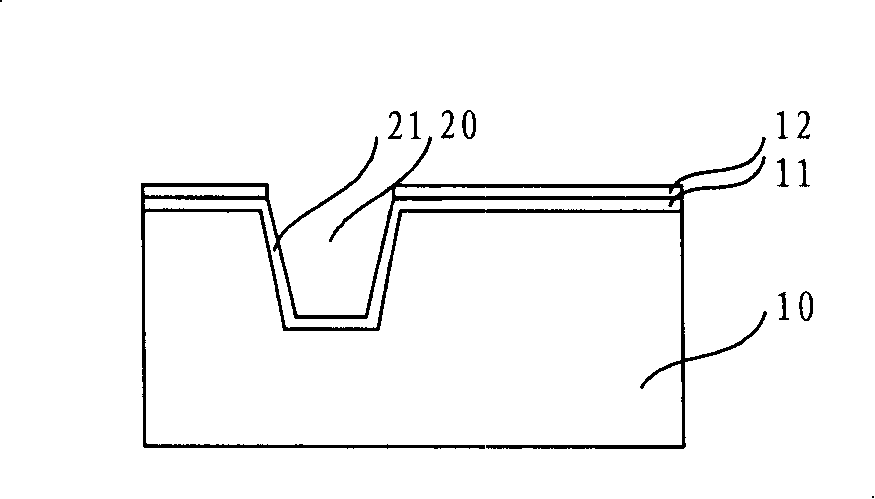
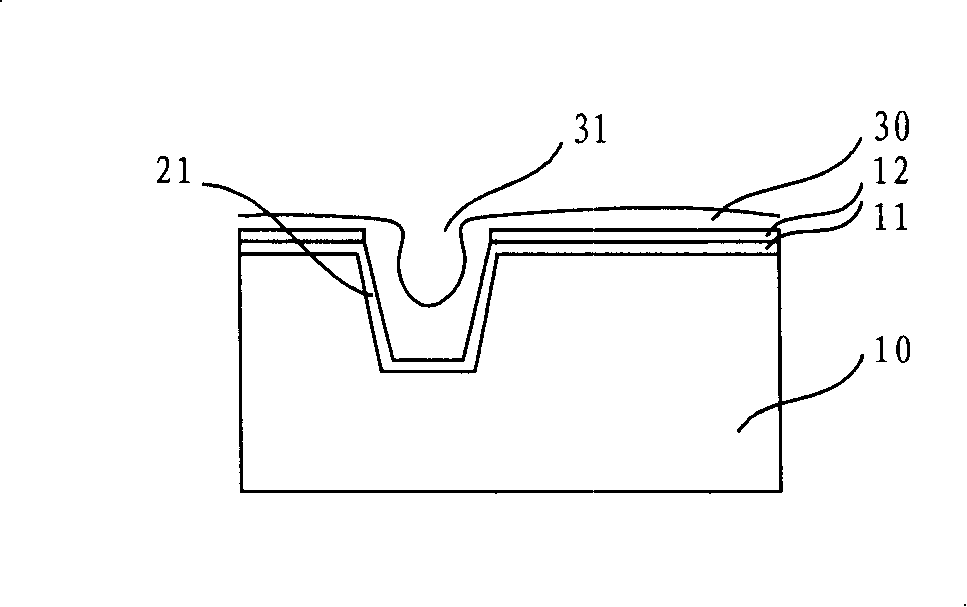
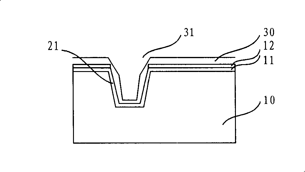
An oxide deposition method of shallow groove isolation area comprises that: a groove is formed on a semiconductor substrate; a sidewall oxide layer is formed on the sidewall and the bottom of the groove; a first oxide layer is deposited on the sidewall oxide layer by low temperature process; the first oxide layer is etched to enlarge a second deposition opening; a second oxide layer is deposited on the first oxide layer. HDPCVD is applied to perform the deposition-etching-deposition technique and can achieve the oxide deposition in the shallow groove isolation area/film layer with no holes; through controlling the temperature of deposition reaction, the density of the deposited film layer can be reduced and further the shallow groove isolation area/film layer oxides with low stress can be achieved.

Description

technical field [0001] The invention relates to the technical field of integrated circuit manufacturing, in particular to an oxide deposition method for shallow trench isolation regions. Background technique [0002] As the integration level of integrated circuits increases, the size of isolation regions between active regions in semiconductor devices must continue to shrink. The traditional area oxidation method (LOCOS) used to isolate the active region has a bird's beak shape at the edge of the field oxide layer due to the oxidation at the edge of the active region, so that between the active regions in the semiconductor device Effective isolation length is limited. Since the above-mentioned disadvantages of the region oxidation method can be avoided, the shallow trench isolation (Shallow Trench Isolation, STI) process has been widely used in isolation between active regions in semiconductor devices in recent years. [0003] In order to ensure the filling effect of STI, ...

Claims


Application Information

Patent Timeline
Patent Type & Authority Applications(China)
IPC IPC(8): H01L21/762
Inventor 张文广
Owner SEMICON MFG INT (SHANGHAI) CORP
Why Eureka
Try Eureka