Low noise divider

A technology of clock frequency divider and frequency division clock, which is applied in the direction of automatic power control, pulse technology, electrical components, etc., and can solve problems such as increasing power supply, phase noise, and edge positioning uncertainty

Inactive Publication Date: 2008-06-11
盟缔杰公司
View PDF1 Cites 4 Cited by
  • Summary
  • Abstract
  • Description
  • Claims
  • Application Information

AI Technical Summary

Problems solved by technology

[0009] Low-noise designs may utilize better circuits than simple CMOS stages containing source followers, CML gates, differential amplifiers, pseudo-NMOS gates, and dynamic CMOS gates, but all of these circuits share a common feature: FET devices spend their time Some of the time is spent in the highly noise-saturated region of operation, where pinching off the channel causes uncertainty in edge positioning and thus phase noise
Increasing device size reduces noise, but at the expense of power; oscillators, buffers, and frequency dividers must be much larger than the minimum size, and very small capacitors in the circuit are also driven adiabatically, increasing the power required power of

Method used


Image

  • Low noise divider
  • Low noise divider
  • Low noise divider

Examples


Embodiment Construction

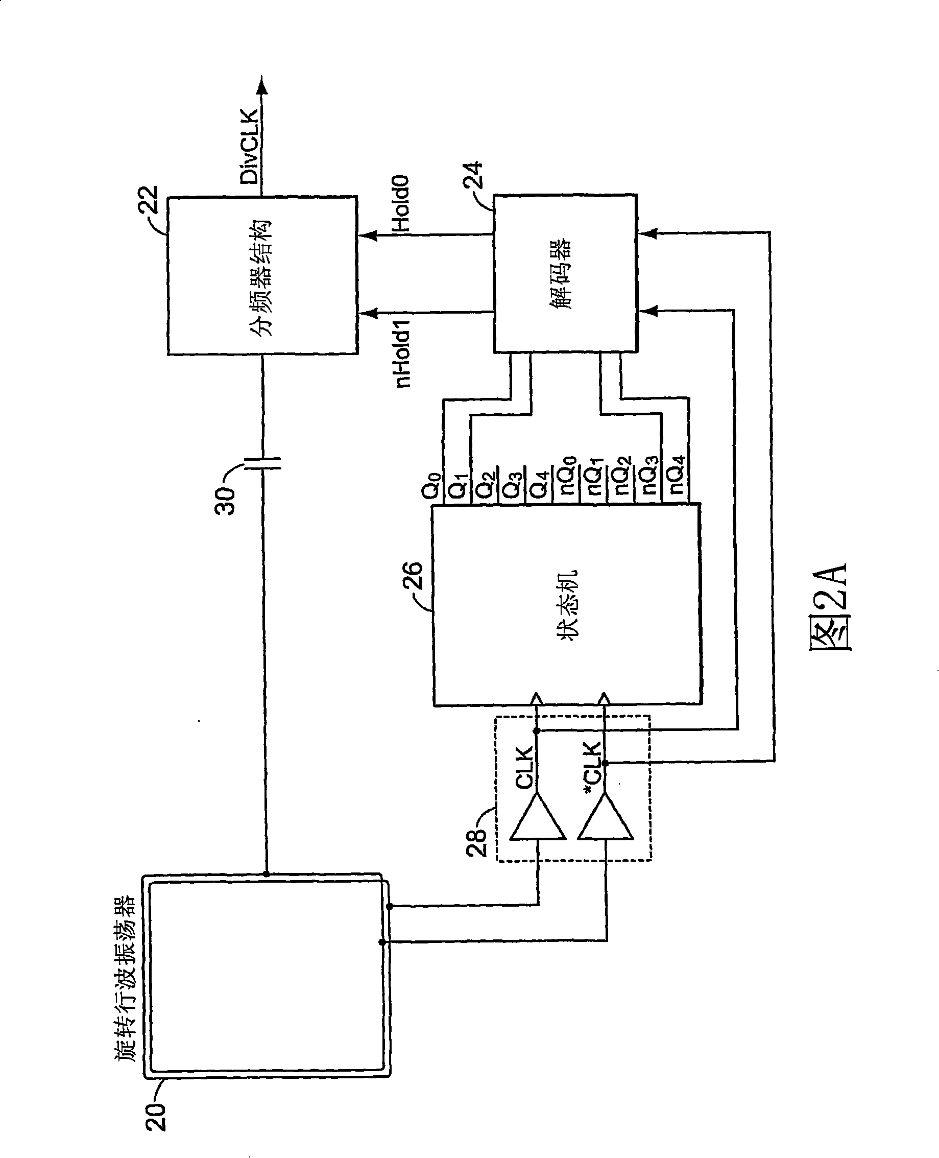
[0025] Figure 2A shows a block diagram of one embodiment of a low noise clock divider. The block diagram includes a multiphase oscillator 20 (such as the rotating traveling wave oscillator of U.S. Patent No. 6,556,089 (incorporated by reference)), a frequency divider structure 22, a decoder 24, a state machine 26, and a clock buffer 28. One branch of the multiphase oscillator is directly connected to the frequency divider structure 22 via capacitor 30, the output of which is DIVCLK. Divider structure 22 receives a pair of signals nHold1 and Hold0 from decoder 24 , which determine when the DIVCLK output is allowed to follow multiphase oscillator 20 . Decoder 24 receives signals from state machine 26 clocked by multiphase oscillator 20 , and receives a clock from multiphase oscillator 20 via clock buffer 28 . State machine 26 is driven by the same pair of clocks as decoder 24 . In one version, the state machine is a "one-hot" state machine, ie, it advances a single "1" (or "0...


PUM


Abstract

A system and method for dividing a clock in a way that achieves low phase noise. In one embodiment, a multi-phase oscillator such as a rotary traveling wave oscillator operates a state machine which determines times at which a transition of a coupled phase signal of the multi-phase oscillator should be suppressed. Suppression of the transition is performed by a transistor structure that holds the phase signal at a high or a low so that the transition does not occur at the output. Fewer transitions in the phase signal create a divided clock. In another embodiment, a decoder determines times for suppressing transitions in a true and complement clock and a polarity flip-flop determines the correct polarity for suppressing edges on both clocks. In yet another embodiment, a multiplexer is used to selectively pass either a true or complement clock to an output load.

Description

[0001] Cross References to Related Applications [0002] This application claims priority to US Provisional Application No. 60 / 656,065, filed February 23, 2005, and entitled "LOW NOISE DIVIDER," which is incorporated herein by reference. technical field [0003] The present invention relates generally to clock frequency division, and more particularly to low noise clock dividers. Background technique [0004] Crossovers generally fall into two broad categories. One class is digital, implemented by flip-flop or latch-based state machines. The other category is regenerative. This type of divider is similar to a low-Q oscillator tuned to a divisor of the input frequency, which pumps energy into the regenerative divider, forcing it to lock to a certain sub-harmonic. [0005] When driven by a VCO, both types of dividers exhibit a theoretical phase noise spectrum that appears to be identical to the oscillator's input phase noise spectrum, but shifted down by 20log(N) dB. As a...

Claims


Application Information

Patent Timeline
Patent Type & Authority Applications(China)
IPC IPC(8): H03K21/00H03L7/18
CPCH03K21/00H03B5/1852
Inventor 约翰·伍德
Owner 盟缔杰公司
Why Eureka
Try Eureka