Electro-optical system for implementing multiple CCD seamless concatenation using prismatic decomposition vignetting compensation

An optoelectronic system and seamless splicing technology, applied in the field of optoelectronic systems, can solve the problem of high cost of lenses

Inactive Publication Date: 2008-06-18
ZHEJIANG UNIV
View PDF0 Cites 35 Cited by
  • Summary
  • Abstract
  • Description
  • Claims
  • Application Information

AI Technical Summary

Problems solved by technology

However, this method requires multiple lenses. Under the requirements of high-pixel and large-fiel

Method used


Image

  • Electro-optical system for implementing multiple CCD seamless concatenation using prismatic decomposition vignetting compensation
  • Electro-optical system for implementing multiple CCD seamless concatenation using prismatic decomposition vignetting compensation
  • Electro-optical system for implementing multiple CCD seamless concatenation using prismatic decomposition vignetting compensation

Examples


Embodiment Construction

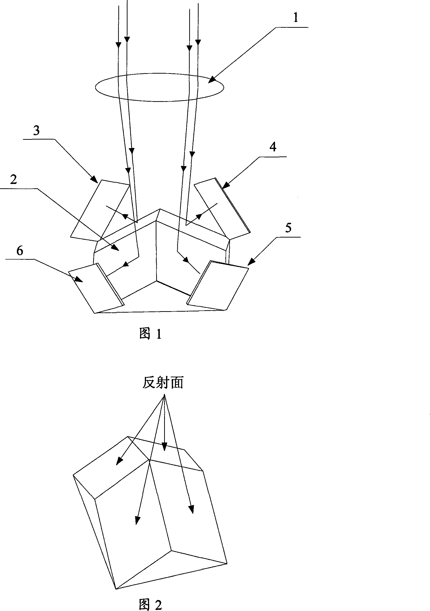
[0027] Fig. 1 shows the composition diagram of the photoelectric system of the present invention. 1 is a large field of view imaging lens, 2 is a beam splitting prism, 3 is the first CCD, 4 is the second CCD, 5 is the third CCD, and 6 is the fourth CCD. Dichroic prism 2 separates four parts from the image plane of imaging lens 1 into four positions in space, and these four positions respectively house CCD 3 , CCD 4 , CCD 5 and CCD 6 .

[0028] The dichroic prism 2 is placed behind the imaging lens 1 and close to the image plane in front of the imaging lens. The four reflective surfaces of the dichroic prism 2 are coated with a high-reflectivity film, which reflects the four parts of the image surface to four positions in space respectively, and a CCD (as shown in Figure 1 ) is respectively placed on these four spatial positions. From the perspective of spatial position, the four CCDs are not on the same plane, and the placement of the CCDs will not interfere with the non-phot...


PUM


Abstract

The invention discloses an opto-electrical system which realize seamless matching of multiple CCDs with prism light splitting vignetting compensation; the invention comprises an imaging lens for receiving external image surface (namely external image data), a light splitting prism for receiving, cutting up and reflecting the image surface from the imaging lens as well as a CCD for receiving the image surface from the light splitting prism (equipped with a circuit board of the CCD). The opto-electrical system of the invention receives light energy with vignetting viewing field with the help of few overlapping of the CCD viewing field and the vignetting phenomenon is compensated by the overlapping part of the sub-image surface combined with algorithm of software. The imaging system of the opto-electrical system of the invention with no movement component, no deficiency of the imaging viewing field, no large vignetting viewing field and high pixel data has enormous significance. The invention is suitable for the field with requirement for the long-distance imaging system of large viewing field and high resolving capability, such as remote sensing by satellite, photo by seaplane, air defense with infrared reconnaissance, etc.

Description

technical field [0001] The invention relates to a large-field-of-view CCD seamless splicing technology, in particular to an optoelectronic system for realizing multi-CCD seamless splicing by utilizing prism splitting and vignetting compensation. Background technique [0002] As an image sensor, CCD (Charge Coupled Device) is widely used in image acquisition fields and systems such as aerial photography, remote sensing, ordinary digital cameras, and infrared imaging systems. Digital imaging systems using CCD as image sensing receivers are developing rapidly. , but due to the limitation of the number of pixels of the CCD device, even if the optical imaging lens has a very large field of view and high resolution, it is still difficult for the system to obtain a large amount of information. Taking the long-wave infrared CCD imaging system as an example, at present, the highest pixel of the uncooled device that can be opened to my country in the world is 384×288, and the imaging ...

Claims


Application Information

Patent Timeline
IPC IPC(8): G02B27/10G02B27/14H04N5/335H04N5/374H04N5/3745
Inventor 冯华君雷华徐之海李奇
Owner ZHEJIANG UNIV
Why Eureka
Try Eureka