Illuminating device capable of adjusting light-rising angle

A light-emitting device and light-emitting angle technology, which is applied to lighting devices, lighting device parts, lighting device safety devices, etc. , the effect of increasing ease

Active Publication Date: 2008-06-25
IND TECH RES INST
View PDF5 Cites 24 Cited by
  • Summary
  • Abstract
  • Description
  • Claims
  • Application Information

AI Technical Summary

Problems solved by technology

[0004] 1. The angle of light projection is limited, so it is not suitable for traditional lamps, and it must be used with a reflective or direct structure cover to emit light;
[0005] 2. The brightness of a single light-emitting diode cannot meet the needs of lamps. Multiple light-emitting diodes with fixed projection angles must be used to emit light to provide sufficient brightness, resulting in uneven light, glare and limited light-emitting range of direct-lit lamps with fixed projection angles. and other issues, causing discomfort to the viewers;
[0006] 3. The light projection angle of the light emitting diode light source is fixed, so it is difficult to adjust different light emission angles and light patterns for different light or needs for refracting or reflective lamps with fixed light projection angles, which is less flexible in use;
[0007] 4. In traditional LED lamps, since the LEDs are fixed on the circuit board, if you need to replace or repair a single LED light source, or change the type of LED configuration, you must disassemble and replace it together with the circuit board. The maintenance method is quite Difficult, it is difficult for ordinary consumers to replace or repair by themselves
[0013] Due to the shortcomings of the limited light projection angle of LED lighting, it cannot be effectively improved at present. In order to control the light emitting angle, light emitting range and light uniformity of LED lighting fixtures, direct-lit LED lamps can only be changed by changing the arrangement of LEDs, or in the LED lighting. The light source is improved by adding a lens, and the refractive or reflective LED lamps are usually designed to control the light angle, light range and light uniformity of the lamp through the design of the refraction or reflector or the replacement of the reflector.
[0014] First of all, as far as direct-type lamps are concerned, although good light output efficiency can be obtained, the light-emitting angle of LEDs cannot be adjusted, resulting in users being unable to adjust the most appropriate light-emitting angle, light-emitting pattern, and uniformity of light in the light-emitting area according to environmental needs. degree, the accompanying light environment comfort is also reduced
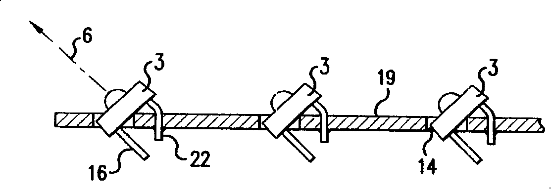
[0015] Cooperating with the two previous patents, a brief description of the light-emitting method of the direct-type LED lamps is given, please refer to Figure 4 , U.S. Patent No. 5136483 Illuminating device, the invention is a lamp applied to vehicles, which includes a plurality of light-emitting diodes 14 placed flat on the inner annular side wall of the lamp, a lamp reflector 16 and cooling fins 19, placed flat on the side wall The light emitted by the light-emitting diode 14 is reflected by the curved reflector (the reflective structure surface with an arc-shaped bottom), which can generate parallel light rays; in this patent, since the light-emitting diode 14 is placed flat inside the lamp Above the side wall, only a part of the light emitting angle range of the light emitting diode 14 can be reflected by the reflector 16 to generate parallel light rays, and the light rays in other light emitting angle ranges are emitted at undesired light angles, or are trapped It cannot be projected inside the lamp, so it cannot efficiently project the light required by the user
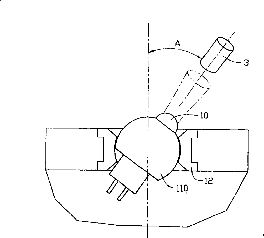
[0016] see again Figure 5 , Japanese Invention Patent Laid-Open No. 2004327670, which discloses a tiltable and rotatable light-emitting diode lamp. The angle of rotation between the foot assembly 11 and the lamp body 10 changes the angle between the light-emitting diode 1 and the substrate 2 to obtain light in different directions; in this patent, since the light is directly irradiated without any refraction or reflection device, it is easy to generate glare , and the adjustable angle is limited between 0° and 90°. If there is light in other directions, another set of devices needs to be used together; inconvenient

Method used


Image

  • Illuminating device capable of adjusting light-rising angle
  • Illuminating device capable of adjusting light-rising angle
  • Illuminating device capable of adjusting light-rising angle

Examples


Embodiment Construction

[0070] The technical means and effects used by the present invention to achieve the purpose will be described below with reference to the accompanying drawings, and the embodiments listed in the following drawings are only for auxiliary description, to facilitate understanding, but the technical means of the present invention are not limited to Figures listed.

[0071] see Image 6 As shown, the refraction light emitting device 10 provided by the present invention with adjustable light output angle includes at least one light emitting diode 20, which is a directional light source. In other words, the light emitting diode 20 can be other types of directional light source Instead, light-emitting diodes are used here as an example for illustration. The light-emitting diodes 20 are electrically connected to a control circuit (not shown in the figure) to emit light, and the direction of the light projection is adjustable. The specific structure that the light emitting direction of...


PUM


Abstract

The invention relates to a luminescent device capable of adjusting light emitting angles which comprises at least one directional light source and a light guide shade, wherein, the directional light source can emit light when electrically conducted with a control circuit, and the projection angle of the directional light source is adjustable; the light guide shade is provided with the directional light source inside and a light control microstructure inside, and the light control microstructure is formed by a plurality of microstructural surfaces provided with refraction or reflection property; through adjusting the projection angle of light emitted by the directional light source, the light can project to the different microstructural surfaces on the light control microstructure, thereby changing the light emitting angle of the light emitted from the light guide shade.

Description

technical field [0001] The present invention relates to a light-emitting device capable of adjusting the light-emitting angle, in particular to a light-emitting device that uses a light-emitting diode as a light source and cooperates with a light-controlling microstructure light guide cover. By adjusting the light-emitting angle of the light-emitting diode, the light output of the light-emitting device can be changed. A light-emitting device with an adjustable light-emitting angle. Background technique [0002] Traditional light sources can be divided into two types: point light sources and line light sources. Tungsten filament lamps and energy-saving bulbs are point light sources, while fluorescent tubes are line light sources. When the above two light sources emit light, they emit light in a radial manner. Therefore, it is impossible to adjust the projection angle of the light source. [0003] In recent years, light-emitting diodes (LEDs, Light Emitting Diodes), which hav...

Claims


Application Information

Patent Timeline
Patent Type & Authority Applications(China)
IPC IPC(8): F21S2/00F21V13/02F21V3/00F21V3/04F21V7/22F21V14/02F21V23/00F21V25/10F21Y101/02F21K9/20F21K9/68F21K9/69F21Y115/10
Inventor 赖杰隆林建宪李丽玲李宏俊
Owner IND TECH RES INST
Why Eureka
Try Eureka