Bistable microcomputer electric relay

A relay, bistable technology, applied in the direction of electromagnetic relay, relay, electromagnetic relay detailed information, etc., can solve the difficulty of making high-efficiency coils and permanent magnets, small, generally in the order of microns, the performance and price of micro-electromechanical relays cannot be. To meet market demand and other issues, to achieve high-efficiency symmetrical bistable, short response time, and improved electrical performance

Inactive Publication Date: 2008-06-25
CHONGQING UNIV
View PDF4 Cites 19 Cited by
  • Summary
  • Abstract
  • Description
  • Claims
  • Application Information

AI Technical Summary

Problems solved by technology

Existing micro-electromechanical relays usually adopt on-chip integration technology based on multi-layer film technology and sacrificial layer technology. This technology has great limitations, such as the difficulty in making high-efficiency coils and permanent magnets, and the structural size of contact electrodes. And and the suspension height is small, generally in the order of microns, and the surface adhesion effect is relatively prominent, so that the performance and price of the MEMS relay cannot meet the market demand

Method used


Image

  • Bistable microcomputer electric relay
  • Bistable microcomputer electric relay
  • Bistable microcomputer electric relay

Examples


Embodiment Construction

[0065] The four bistable micro-electromechanical relays are described in detail below in conjunction with the accompanying drawings:

[0066] 1. Bistable MEMS relay 1

[0067] Bistable MEMS relays 1 are used for power management and automatic control.

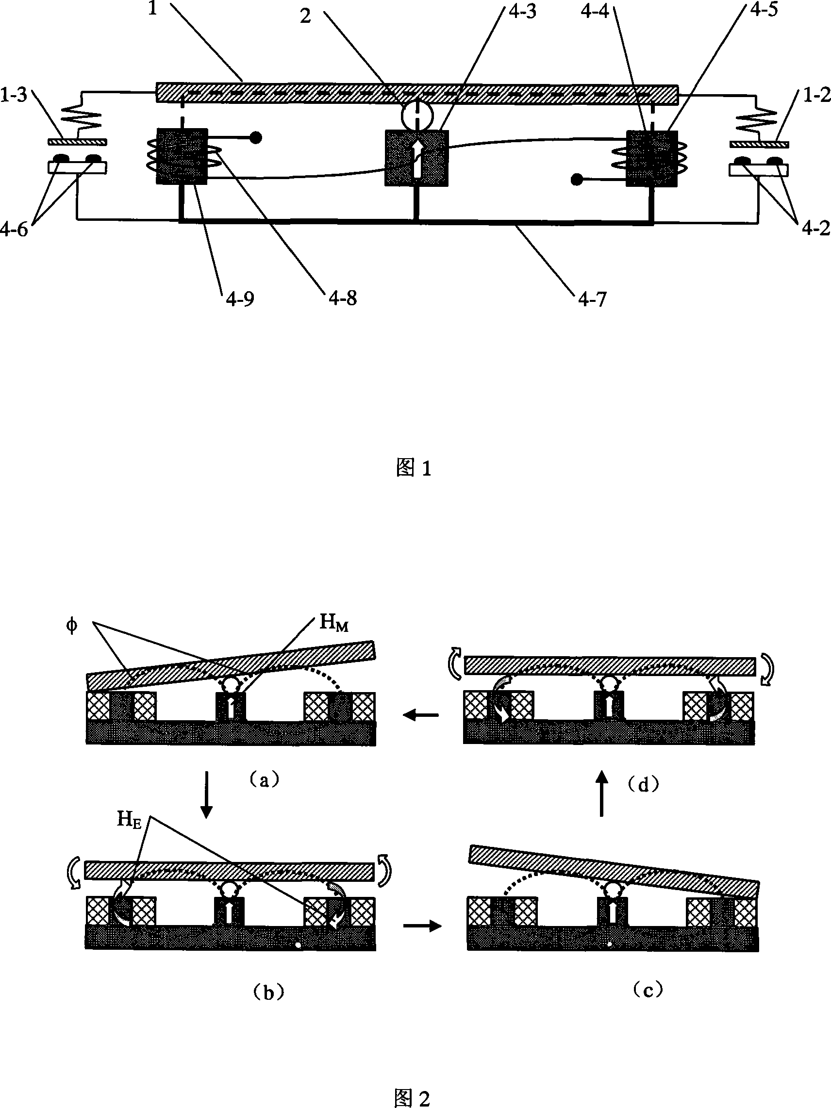
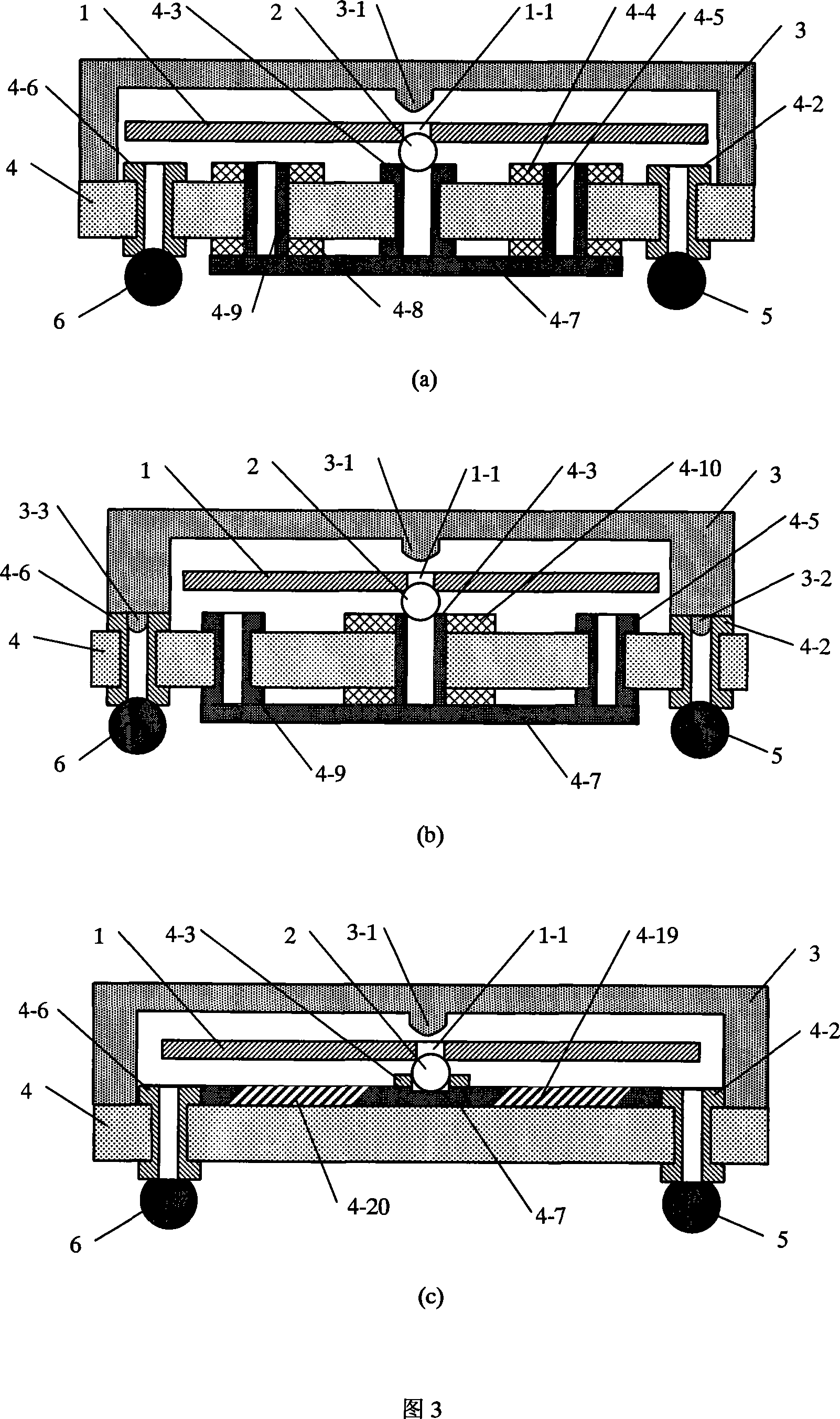
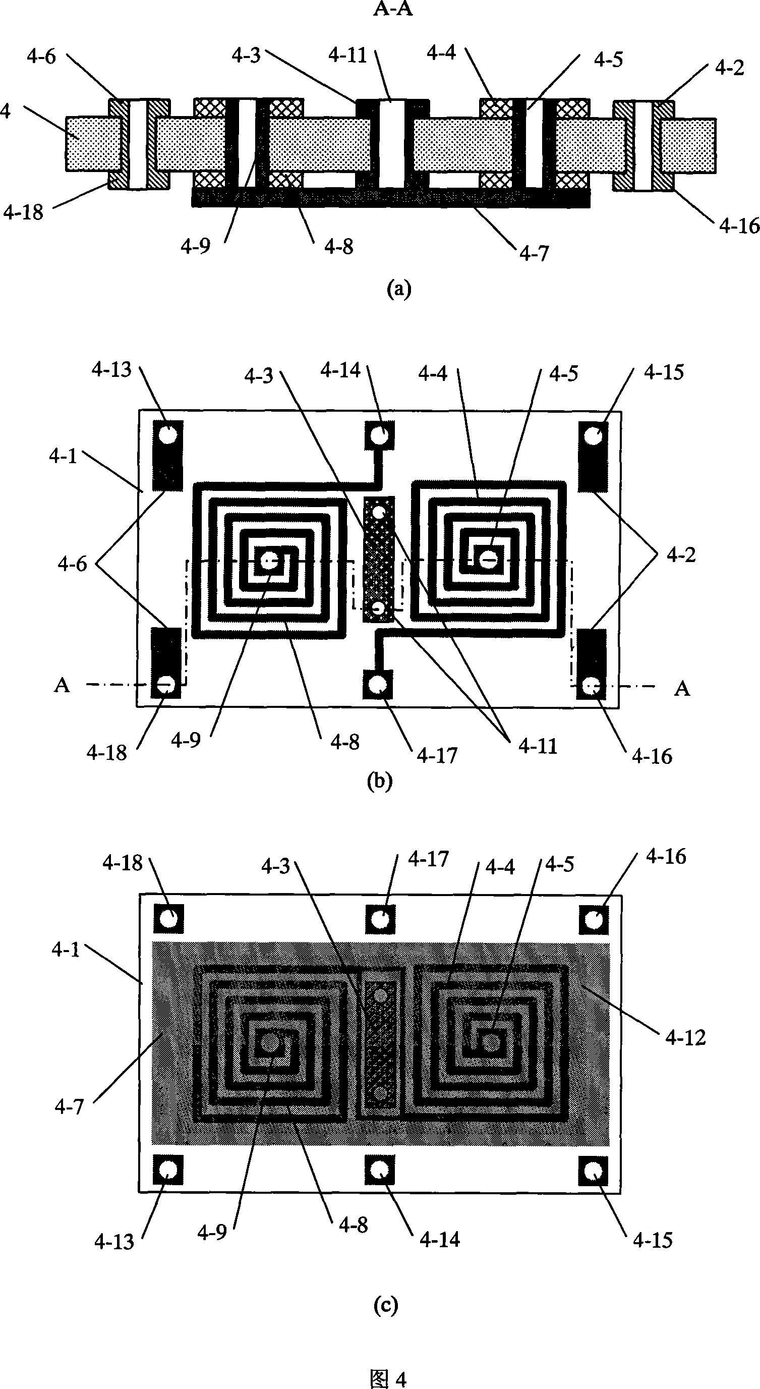
[0068] In Fig. 3 (a), in Fig. 4 (a), (b), (c) and Fig. 5 (a), (b), (c), (d), bistable microelectromechanical relay 1 comprises encapsulation cover 3. Movable diaphragm 1, microsphere 2, electromagnetic substrate 41 and pins.

[0069] In Figure 5(c) and (d), the packaging cover 3 is pressed and sintered by a ceramic material through a mold to grow into a rectangular parallelepiped whose width, width and height are 10mm, 6mm and 0.6mm respectively. Blind holes of 9mm, 4mm, 0.4mm, on the longitudinal axis of the bottom of the package cover 3 opposite to the microsphere 2, there is a ridge 3-1 with a length of 3mm to limit the distance between the movable diaphragm 1 and the microsphere 2 The cross-section of the rib 3-1 is comp...


PUM


Abstract

The invention relates to a bistable micro-electromechanical relay, in particular to a micro miniature relay with state maintaining function, which is mainly applied to systems of power supply management, instruments and meters, automatic control and wide band communication, etc. The relay comprises a packaging cover, a base pin, a movable diaphragm, micro balloons and an electromagnetic base plate; wherein, the movable diaphragm and the micro balloons are positioned in a hollow cavity formed after the packaging cover, and the electromagnetic base plate are fixedly connected, upper electrodes opposite to the lower electrodes at the left end and the right end of the upper surface of the electromagnetic base plate are respectively arranged at the two ends of the movable diaphragm, round holes are distributed along the longitudinal symmetric axis of the movable diaphragm, and are movably positioned on the corresponding micro balloons, and the microballoons are movably positioned on the round holes of a microballoon base seat on the electromagnetic base plate. The integration level of the relay is high, bistable electromagnetic driving and state locking are realized, the driving energy consumption and the working loss are reduced while the response speed and the service life of the relay are obviously improved, the response time is short, the insulating strength and the compression strength are high, and the work is stable.

Description

technical field [0001] The invention relates to a miniaturized electromechanical relay with state holding function, which is mainly used in systems such as power supply management, instrumentation, automatic control and broadband communication. Background technique [0002] As a basic electromechanical component, miniature relays are widely used in power management, instrumentation, automatic control and communication systems. Typical applications are wide bandwidth (DC-10GHz), wide load (DC10mV10mA-2A50V) line switching, low insertion loss, high isolation radio frequency communication, low energy consumption, fast response electromechanical control, and electromechanical relays that require a large amount of miniaturization, Arrayed places, such as communication switches and backup line switching systems, automotive control systems, etc. These applications place higher demands on the performance of miniature relays. [0003] The working principle of the electromechanical ...

Claims


Application Information

Patent Timeline
Patent Type & Authority Applications(China)
IPC IPC(8): H01H50/16H01H50/64H01H50/02
Inventor 张流强
Owner CHONGQING UNIV
Why Eureka
Try Eureka