
Automatic arranging device for arrangement steel nails

An automatic, row-by-row technology, applied in packaging, transportation and packaging, conveyor objects, etc., can solve the problems of steel row nails that cannot be automated production, steel nails that are easy to agglomerate and difficult to arrange, etc.

Inactive Publication Date: 2008-07-02
HENAN AGRICULTURAL UNIVERSITY
View PDF0 Cites 7 Cited by
  • Summary
  • Abstract
  • Description
  • Claims
  • Application Information

AI Technical Summary

Problems solved by technology

[0003] At present, the market demand for steel nails is very large, but the production scale of steel nails is still very small, because the steel nails cannot be automated.
Because it is difficult to automatically arrange the steel nails in the automatic production process, a pile of messy steel nails tend to agglomerate and have special shapes, so it is not easy to arrange

Method used


Image

  • Automatic arranging device for arrangement steel nails
  • Automatic arranging device for arrangement steel nails
  • Automatic arranging device for arrangement steel nails

Examples


Embodiment 1

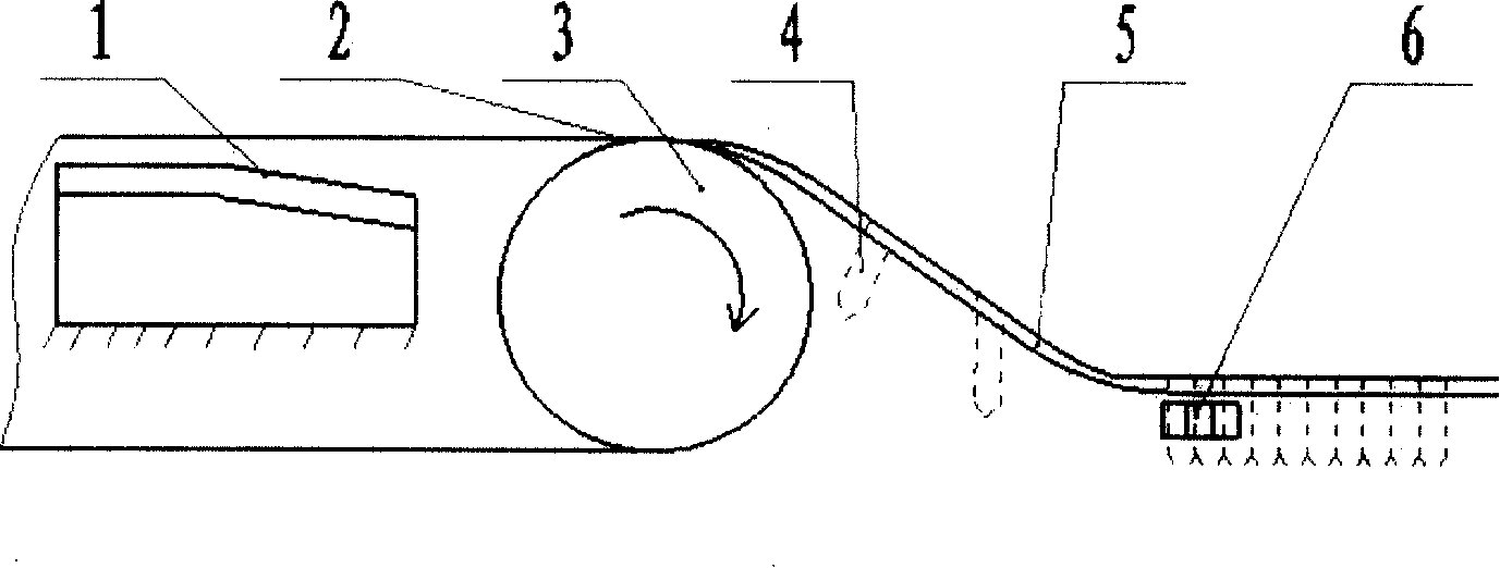
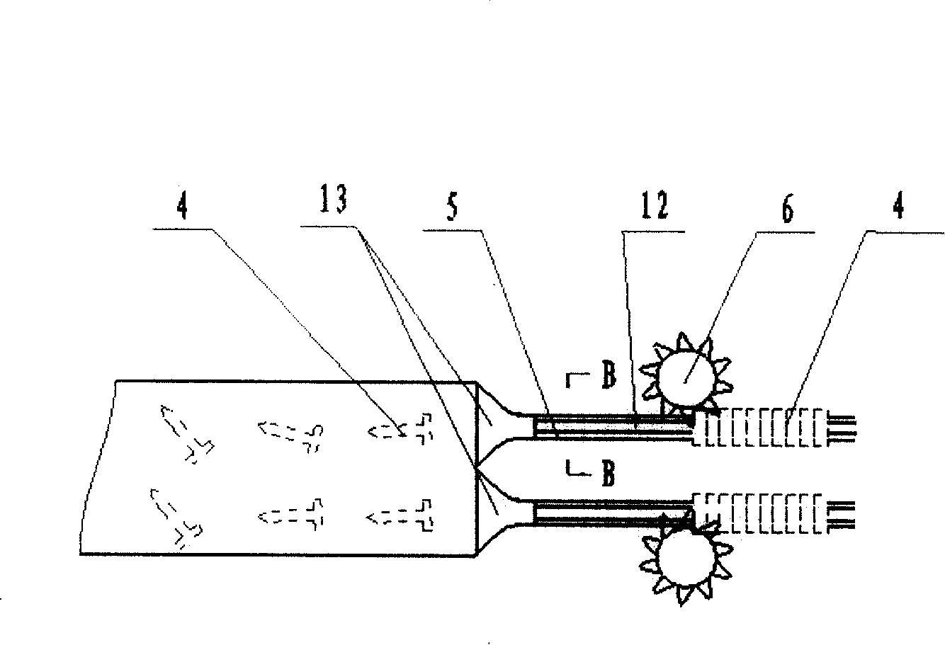
[0021] Such as figure 1 , 2 As shown, the automatic nail arranging device of this steel includes a strip magnet 1, a pulley 3 and a conveyor belt 2 installed on the pulley 3. The strip magnet 1 is located below the conveyor belt 2 and is attached to the inside of the upper surface of the conveyor belt 2. Shaped magnetic steel 1 upper surface is combined by straight plane and inclined plane, and straight plane is level, and inclined plane is high in front and low in back. Two rows of slideways 5 are arranged side by side at the rear of the conveyor belt 2, and a collecting bucket 13 is arranged at the head of the two rows of slideways 5 to be tangent to the end of the conveyor belt 2. The rear part is placed horizontally, and a ratchet 6 is respectively established on the side of the horizontal part. Such as Figure 4 Shown, slideway 5 bottom surface has the slit 12 that is bigger than steel nail diameter less than steel nail cap width size, and the ratchet 6 that is positi...

Embodiment 2

[0024] Such as Figure 5 , 6 As shown, the automatic nail arranging device of this steel includes a strip magnet 1, a pulley 3 and a conveyor belt 2 installed on the pulley 3. The strip magnet 1 is located below the conveyor belt 2 and is attached to the inside of the upper surface of the conveyor belt 2. The upper surface of shaped magnetic steel 1 is composed of a straight plane and an inclined plane, the straight plane is horizontal, and the inclined plane is high at the front and low at the rear. The end of the conveyor belt 2 is horizontally connected with a slideway 5, and the end of the slideway 5 turns horizontally to 90 degrees to form a corner slideway 11. The rear corner side of the slideway 5 is provided with an eccentric wheel 7 and a push rod 10, and the push rod 10 is covered Back-moving spring 8 is arranged, and spring 8 is supported on the baffle plate 9 of corner slideway 11 sides, and push rod 10 is perpendicular to slideway 5, is parallel to corner slidewa...


PUM


Abstract

The invention discloses an automatic rowing-up device for producing 'T'-shaped steel chain rivets which consists of a strip alnico, a belt wheel and a conveyor belt arranged on the belt wheel. The strip alnico is arranged below the conveyor belt and partially adhered to the inner side of the upper surface of the conveyor belt and is tangentially connected with the tail end of the conveyor belt and provided with a slideway. The back part of the slideway is provided with a steel nail collecting mechanism. Disorder 'T'-shaped steel nails falling on the rowing-up device move backwards with the conveyor belt and when passing through the strip alnico and under the double actions of friction and magnetic force, the friction loaded by head parts of the 'T'-shaped steel nails is larger than that of the nips of the steel nails, thus the 'T'-shaped steel nails can automatically arrange in a mode that the nail head is behind and the nail tip is front; and then under the action of steel nail collecting mechanism, the steel nails are extruded into a row and then are sized and made into the steel chain rivets. The invention leads the steel chain rivets production to realize autoimmunization, improves the productivity effect and reduces the working intensity.

Description

technical field [0001] The invention relates to an automatic arranging device for manufacturing "T"-shaped steel row nails. Background technique [0002] At present, the production process of steel nails: first produce a single steel nail, the production process is as follows: take the coiled wire (high, medium or low carbon steel) as the raw material, and pull (cold drawn) several times through the wire drawing machine to the steel nail For the required wire diameter, the steel nails are produced by the nail making machine, quenched in the heat treatment furnace, polished by the polishing machine, and then electroplated by the galvanizing equipment. Workers arrange the produced steel nails in a row as required image 3 As shown, the final glue is made into a qualified product. [0003] At present, the market demand for steel nails is very large, but the production scale of steel nails is still very small, because the steel nails cannot be produced automatically. Because i...

Claims


Application Information

Patent Timeline
Patent Type & Authority Applications(China)
IPC IPC(8): B65B35/30B65B15/00B65G47/22
Inventor 刘存祥王文堂
Owner HENAN AGRICULTURAL UNIVERSITY
Learn More