Cigarette lighter nozzle manufacture method and mould for the method

A manufacturing method and technology for lighters, applied in the field of lighter parts, can solve the problems of easy corrosion of zinc-aluminum gas nozzles, difficult processing, and high rate of broken ends, and achieve the advantages of less manufacturing technical processes, stable product quality, and reduced material loss. Effect

Inactive Publication Date: 2008-07-09
徐伟明
View PDF2 Cites 5 Cited by
  • Summary
  • Abstract
  • Description
  • Claims
  • Application Information

AI Technical Summary

Problems solved by technology

Its shortcomings are: high raw material prices, large material loss, many processing procedures, high processing costs and low production efficiency, and the copper nozzle also has the problem that the springboard groove is easy to wear and affect the quality of the product.
Its disadvantages are: high processing cost and low production efficiency; although the price of raw materials is lower than that of copper rods, it is still high; due to the problem of uneven pressure and flow during die-casting, it will make the molecules in the nozzle The structure is uneven, and the end-break rate of the finished product after assembly is high when it is inflated, which is likely to cause the whole machine to be scrapped; the springboard groove is also easy to wear and affect the quality of the lighter; The part of the tank wall is easily broken and the user cannot use it
It has high requirements on the ductility of raw materials, the processing is difficult, and there is a problem of material loss in the drilling process

Method used


Image

  • Cigarette lighter nozzle manufacture method and mould for the method
  • Cigarette lighter nozzle manufacture method and mould for the method
  • Cigarette lighter nozzle manufacture method and mould for the method

Examples


Embodiment Construction

[0052] The present invention will be further described in detail below in conjunction with the accompanying drawings and embodiments.

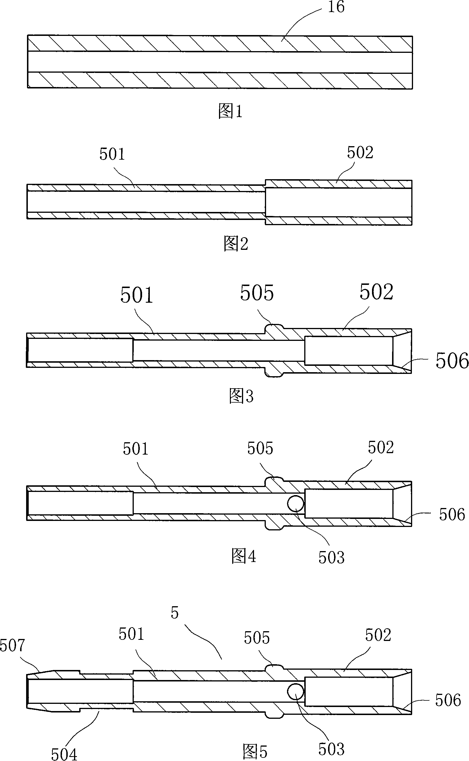
[0053] As shown in Figure 5, the nozzle 5 has a front part 501 with a smaller outer diameter, a rear part 502 with a larger outer diameter, a transverse hole 503 and a springboard groove 504, and the junction of the front part 501 and the rear part 502 has a rear part with a smaller outer diameter. 502 a larger shoulder ring 505 , the rear end of the nozzle 5 also has an inner hole chamfer 506 , and the front end of the nozzle 5 has an outer chamfer 507 .

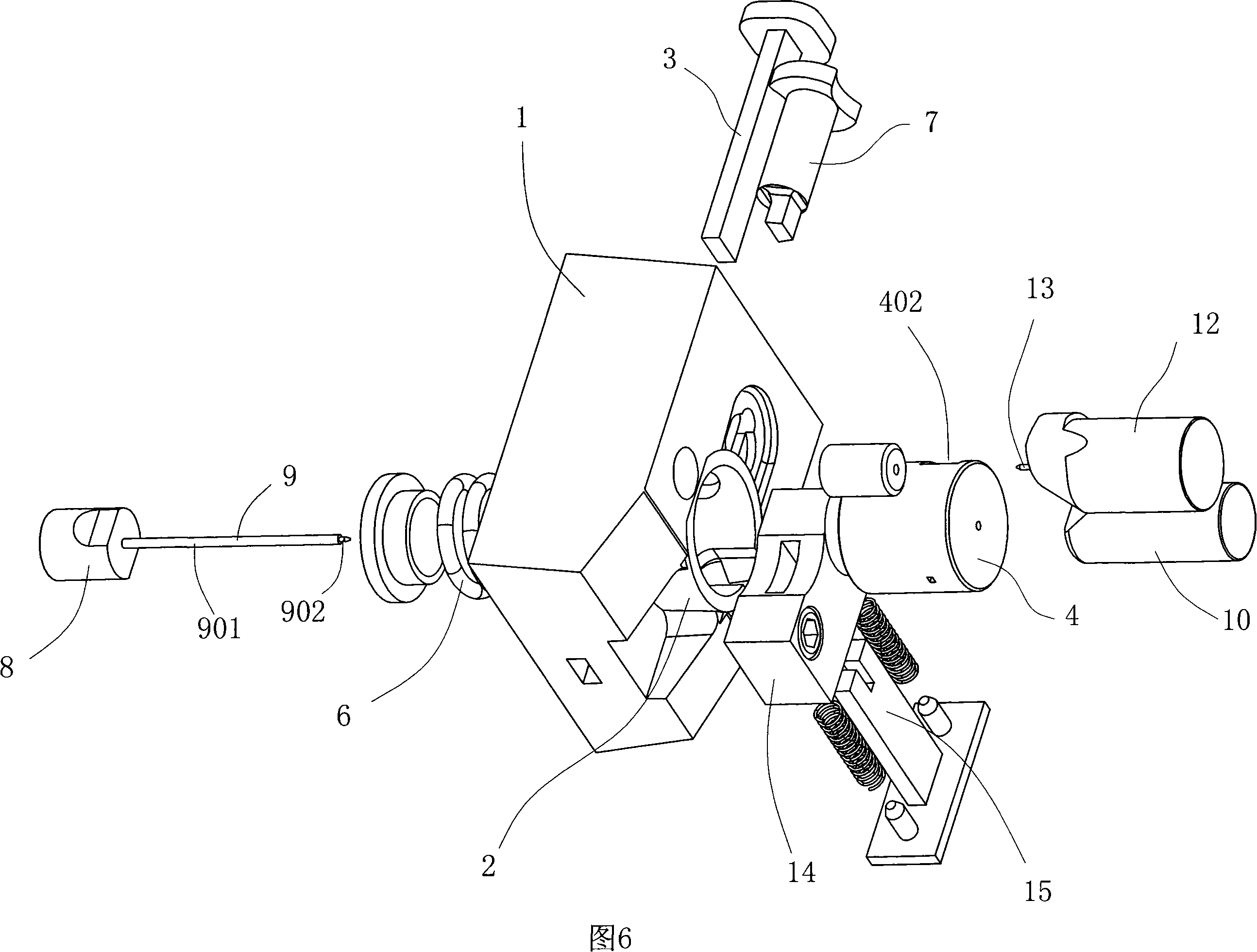
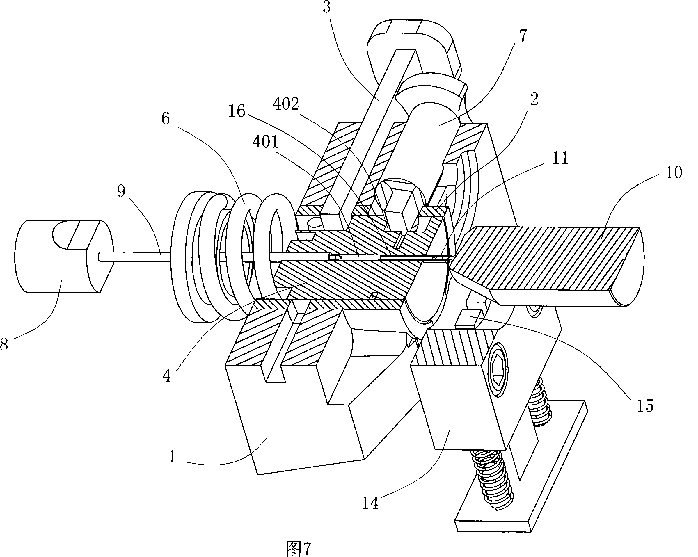
[0054] As shown in Fig. 6~Fig. 16, the structure of mold of the present invention is as follows:

[0055] It includes:

[0056] A seat, the seat includes a seat body 1 and a sleeve 2 embedded in the seat body 1, the inner cavity of the sleeve 2 is provided with a through hole, and the seat body 1 is also provided with a 2. The second lock 3 fixed in the seat body 1;

[0057] A first mold...


PUM

PropertyMeasurementUnit
tensile strengthaaaaaaaaaa
thicknessaaaaaaaaaa
thicknessaaaaaaaaaa

Abstract

The invention discloses a lighter nozzle manufacturing method and a mould for the method. The manufacturing method is supported with low carbon steel tubes as raw materials; the invention comprises such steps as cutting, cold heading, horizontal hole-punching and catwalk slot machining and etc. The mould, however, comprises a support, a first mould, a resetting spring, a first staple, a second mould, a third mould and a fourth mould; the first mould is assembled inside a through-hole in the support; the interior is opened with the first through-hole in the consistent external diameter as that of the front of the end-product nozzle; the second mould is composed of the second thimble fitting with the first through-hole, so as to form the front part of the nozzle; the fourth mould inside is composed of an aperture in an identical external diameter as that of the rear of the end-product nozzle; the aperture inside is provided with the fourth thimble, in order to form the rear part and the shoulder on the nozzle. The invention method has the advantages of simple technologies, high production efficiency, low raw-material cost and manufacturing expenses, and low consumption of materials and etc; the mould has the advantages of simple structure and convenient use, and therefore, in particular adapting to the manufacturing of lighter nozzles.

Description

technical field [0001] The invention relates to lighter parts, in particular to a manufacturing method of a lighter nozzle and a mold used in the method. Background technique [0002] At present, the competition in the lighter market is very fierce, and price reduction is usually one of the main means of competition for manufacturers. Therefore, how to control or reduce even a little production cost of lighters is of great importance to manufacturers. The nozzle is one of the parts of the lighter, and it is installed at the outlet of the gas storage chamber. When the lighter is in use, the gas in the gas storage chamber is sprayed out through the nozzle and ignited by the ignition mechanism. The manufacturing method of existing lighter nozzle generally has following several: 1, is raw material with copper bar, adopts modes processing moldings such as lathe turning and drilling machine punching. Its shortcomings are: high raw material prices, large material loss, many proce...

Claims


Application Information

Patent Timeline
Patent Type & Authority Applications(China)
IPC IPC(8): F23Q2/16F23Q2/34
Inventor 徐伟明叶波丁忠贵
Owner 徐伟明
Why Eureka
Try Eureka