Backlight module accurate light guide thin film core production method

A technology of backlight module and manufacturing method, which is applied in the directions of light guide, optics, laser, etc., can solve the problems of high technical requirements and difficulty, and achieve the effect of high-efficiency light-guiding structure, process efficiency improvement, and quality stability.

Active Publication Date: 2008-07-09
YANCHENG NICROTEK CO LTD
View PDF1 Cites 19 Cited by
  • Summary
  • Abstract
  • Description
  • Claims
  • Application Information

AI Technical Summary

Problems solved by technology

However, the mask design and manufacture of precision light guide plate mold cores require quite high technical requirements, especially in the production of large-format light guide plates.

Method used


Image

  • Backlight module accurate light guide thin film core production method
  • Backlight module accurate light guide thin film core production method

Examples


Embodiment 1

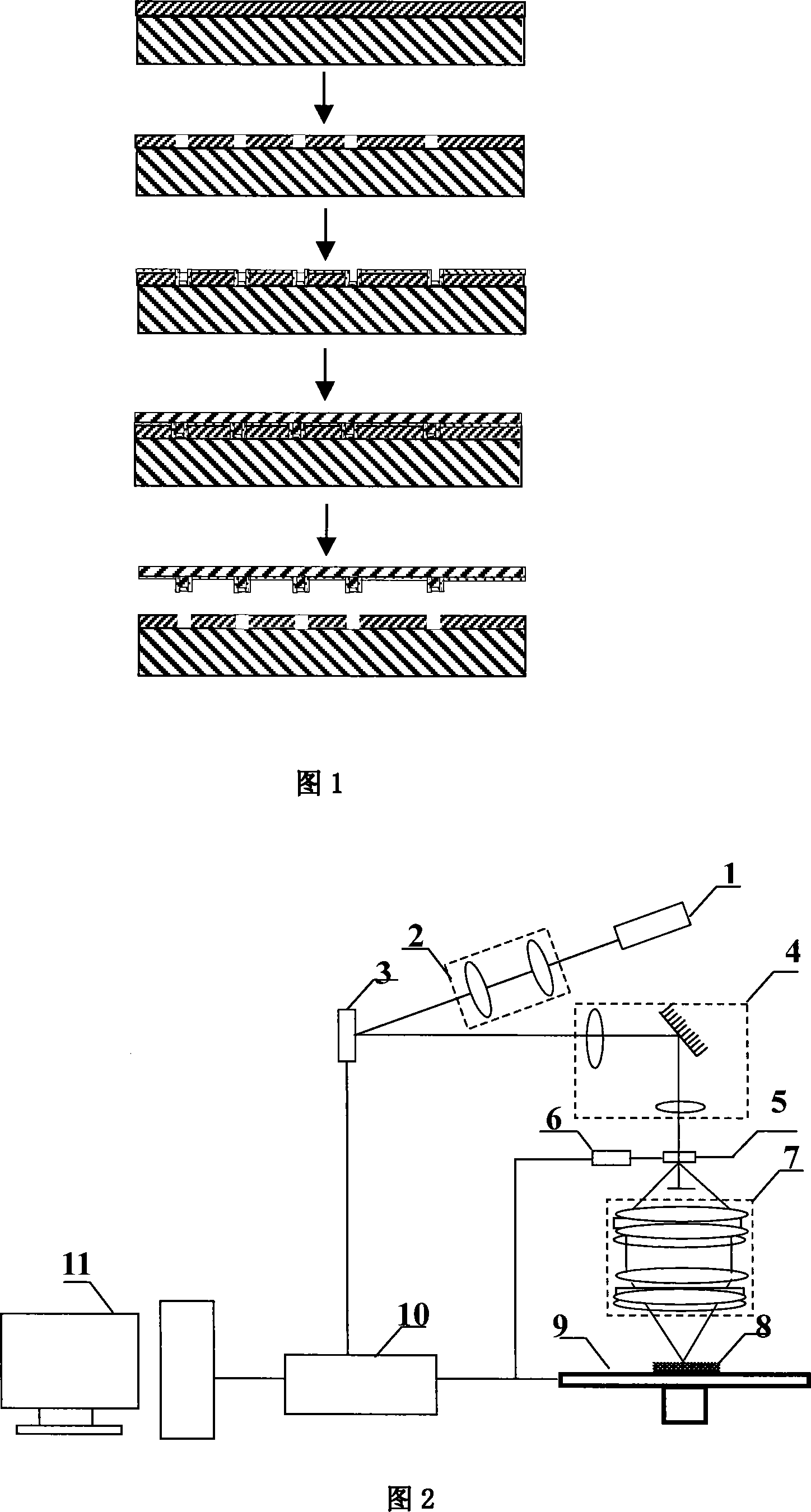
[0045] Embodiment one: referring to shown in accompanying drawing 2, adopt the semiconductor-pumped solid-state laser (DPSSL) 1, ultraviolet light output (triple frequency 351nm / 355nm), single pulse energy>100uJ; Straight system 2, the illumination is on the digital micromirror (DMD) 3, through the projection optical imaging system 4, the figure input on the DMD is reduced, and the magnification of reduction depends on the focal length ratio of the objective lens and the microscope; the reduced figure is imaged on the microscope On the small hole diaphragm 5 on the back focal plane of the rear focal plane, the function of the diaphragm is to block part of the stray light, which is controlled by the diaphragm controller 6; then, the reduced image near the diaphragm is imaged to the SU-8 through the 4F lens group 7 Dry photoresist on plate 8. The photoresist dry plate 8 is set on the x-y precision working platform 9, and is controlled by the precision drive controller 10 to perf...

Embodiment 2

[0056] Embodiment 2: using semiconductor-pumped solid-state laser (DPSSL), ultraviolet light output (frequency tripled 351nm / 355nm), single pulse energy > 100uJ. The laser beam emitted by the laser passes through the beam expansion and collimation optical path, illuminates on the digital micromirror (DMD), and passes through the projection optical system to reduce the input graphics on the DMD. The reduction ratio depends on the focal length ratio of the objective lens and the microscope. The reduced image is imaged on the diaphragm of the back focal plane of the microscope, and the function of the diaphragm is to block part of the stray light. Then, through the 4F lens group, the small figure near the aperture is imaged on the SU-8 photoresist dry plate. By changing the shape of the graphics input on the DMD and the difference in gray scale, the shape of the spot or the distribution of light intensity in the spot can be changed, so that dots with different surface shapes and ...

Embodiment 3

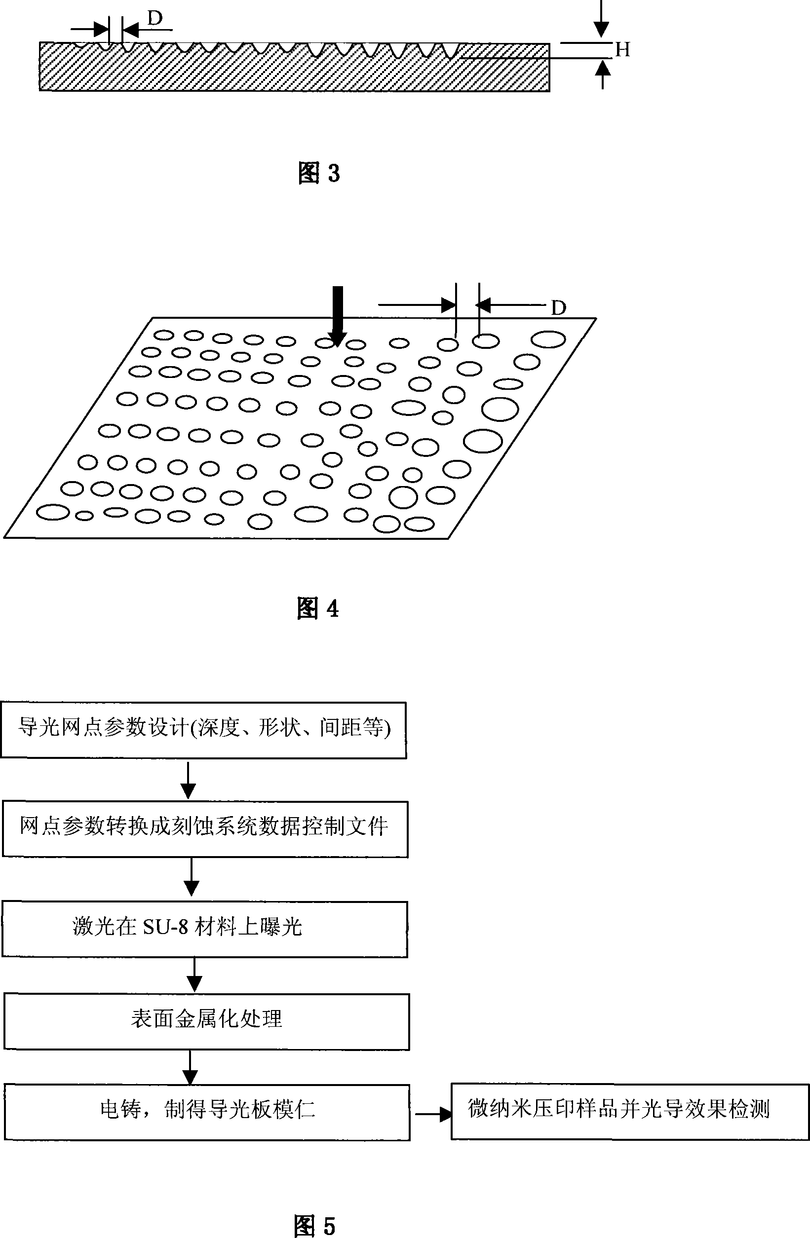
[0057] Embodiment 3: Taking the production of the light guide plate of the display screen of a mobile phone as an example, referring to the accompanying drawing 5, the process steps of the present invention for producing the mold core of the light guide plate (film) are introduced in detail. (1) Design and determine the light guide structure area according to the application requirements, draw the pattern, use the dot design software to design the dot distribution of the light guide area according to the characteristics of the light source, use the optical simulation software to evaluate the luminance and uniformity of the designed dots, and evaluate the dots Do further optimization. Determine the dot size, depth and other parameters. (2) Convert the designed dot distribution and dot parameters into controllable files of laser etching equipment. (3) Adjust the optical path of the laser etching equipment, set the corresponding parameters, and perform etching on the SU-8 dry pl...


PUM

PropertyMeasurementUnit
thicknessaaaaaaaaaa

Abstract

The invention discloses a method for manufacturing a precise photoconductive film cavity of backlight modules, which is characterized in that: an ultraviolet laser beam is reflected on a digital micro mirror after being expanded and collimated, the digital micro mirror is controlled according to the shape of a light guide network to be produced, and reflected light etches the light guide network on the surface of an ultraviolet photoresist dry plate via a projection optical system with 4F light paths; the relative positions of the reflected light and the photoresist dry plate are changed in turn to complete the etching of each needed light guide network; and the etched photoresist dry plate is electroformed after the process of surface metallization, so as to obtain the needed light guide film cavity. By inputting the shape of the light guide network via the digital micro mirror and etching the light guide network on the photoresist dry plate directly via the ultraviolet laser, the invention can evaluate the network design and provide sample products in a rapid manner, and improve the manufacturing quality of the cavity; at the same time, the invention is propitious to the manufacture of large-sized light guide plates.

Description

technical field [0001] The invention relates to a method for manufacturing a mold core of a light guide plate or a light guide film for a liquid crystal backlight module, and realizes a mold core of a light guide plate (light guide film) with high precision, controllable depth and dot size; the mold of the present invention The kernel structure is suitable for the manufacture of light guide plates (light guide films) in LCD displays and large-area backlight modules. Background technique [0002] In recent years, liquid crystal displays (LCDs) have become more and more widely used, and a large area has become a development trend thereof. The LCD itself does not emit light, so the backlight module becomes a necessary component to provide its light emission. The main structure of the backlight module is as follows: light source, light guide plate, diffuser, prism sheet, and reflector. Among them, the light guide plate converts CCFL line light source or LED point light source ...

Claims


Application Information

Patent Timeline
Patent Type & Authority Applications(China)
IPC IPC(8): G03F5/02G03F7/00H01S5/00G02B6/00
Inventor 陈林森
Owner YANCHENG NICROTEK CO LTD
Why Eureka
Try Eureka