Textile machine with yarn monitoring

A textile machine and yarn technology, which is applied in the field of monitoring the yarn at the workstation of the textile machine, and in the field of yarn monitoring system, can solve the problems of complex electronic devices, high price, and inability to intervene in time, and achieve simple functionality, cheap effect

Inactive Publication Date: 2008-07-09
USTER TECHNOLOGIES
View PDF14 Cites 13 Cited by
  • Summary
  • Abstract
  • Description
  • Claims
  • Application Information

AI Technical Summary

Problems solved by technology

The above-mentioned serial data transmission system has the following significant disadvantages: in the event of serious defects, it is impossible to intervene in time
However, due to the complex mechanical structure still required for synchronous data transmission, it ends up making the price ...

Method used


Image

  • Textile machine with yarn monitoring
  • Textile machine with yarn monitoring
  • Textile machine with yarn monitoring

Examples


Embodiment Construction

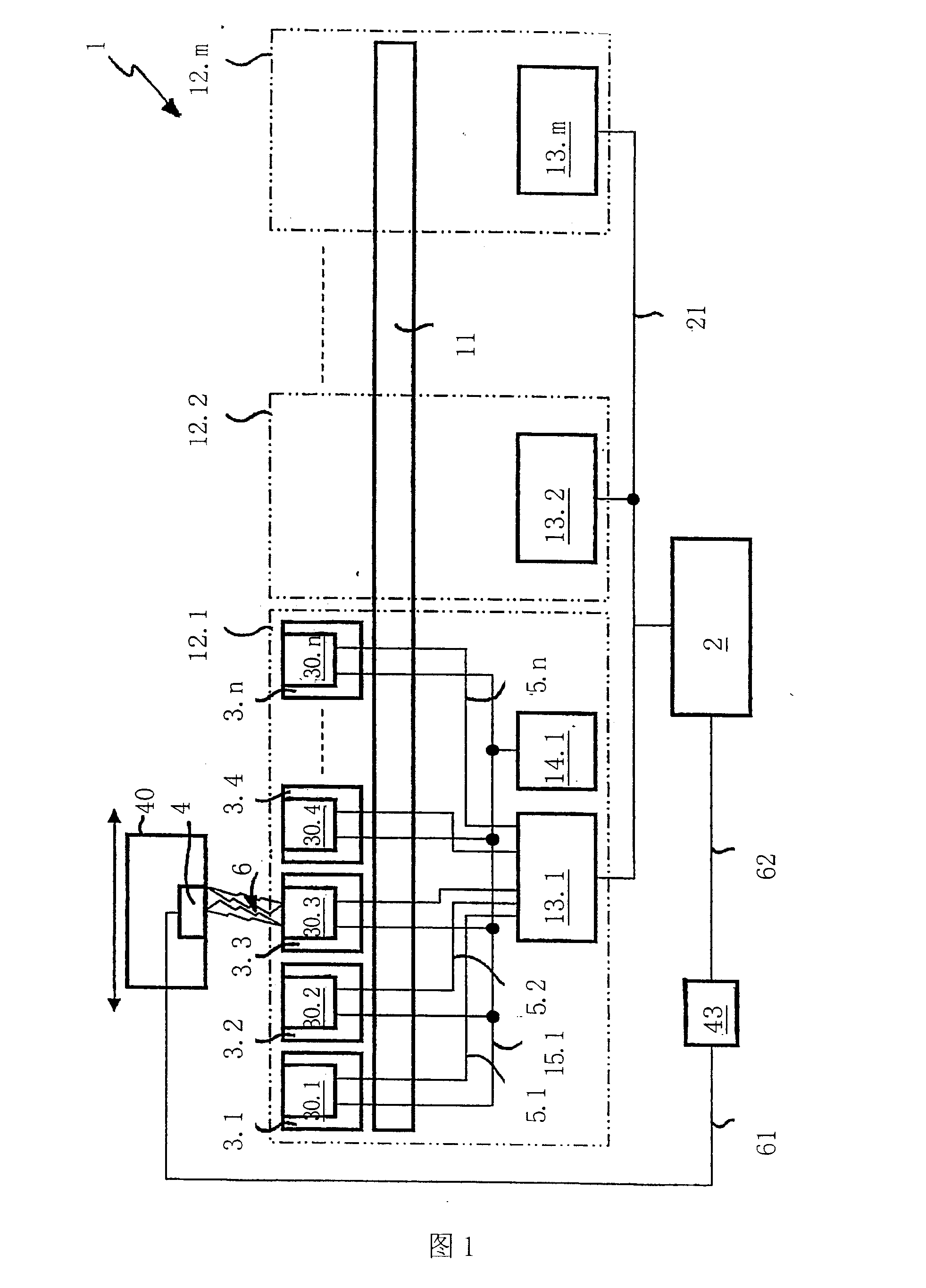
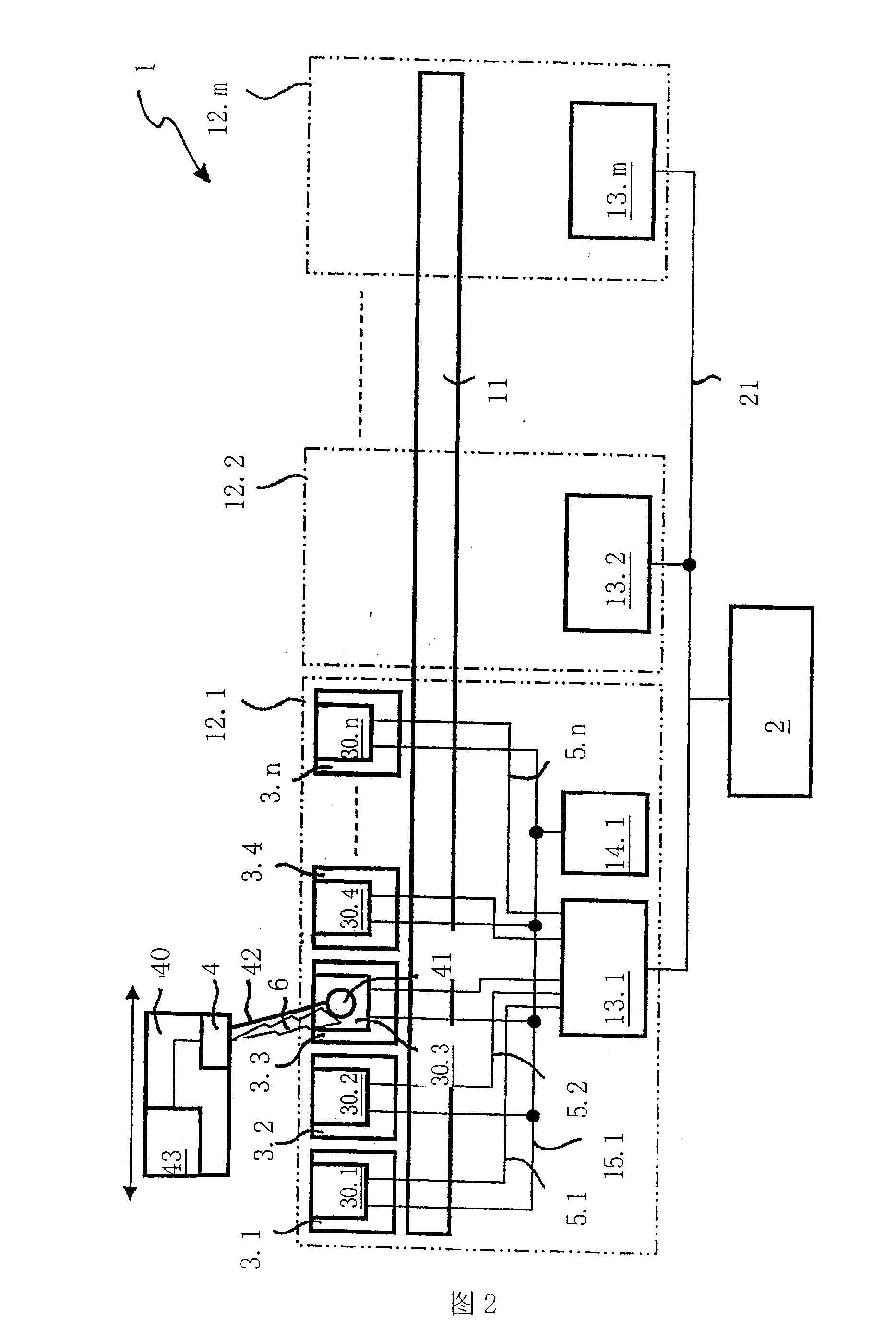
[0029] Figure 1 is a block diagram of various components in a spinning machine 1 according to the underlying invention. The elongated machine frame 11 supports a plurality of spinning units 3.1, 3.2..., 3.n. Modern spinning machines comprise hundreds of such spinning units and these are combined into components 12.1, 12.2..., 12.m every n spinning units. Both m and n are natural numbers, generally m≈16 and n≈20. Unless otherwise indicated, only component 12.1 will be explained in detail below. Of course, these spinning units can also be applied to the special case of m=1, ie a spinning machine without components; and the other parts of the more general case can also be mutated mutatis mutandis. For the sake of simplicity, this figure is only shown schematically in this range, and only the spinning units 3.1, 3.2...m, 3.n are arranged one after the other at one end of the machine frame 11 in this figure. However, under normal circumstances, the spinning unit should preferabl...


PUM


Abstract

A spinning machine (1), comprising a group of spinning units (3.1-3.n), a processor unit (2) and a piecing frame (40). The parallel data transmission device (5.1-5.n) is used for the continuous synchronous transmission of time-critical data between each workstation (3.1-3.n) and the workstation inspection unit (13.1), and the parallel data transmission device can be as simple as possible and cheap way to work. Another serial data transmission device (6) is used to transmit time-non-critical data between the only selected workstation and the splicing carriage. Since the invention divides the transmission data, the textile machine (1) is simpler and cheaper.

Description

field of invention [0001] According to the preambles of the independent claims, the invention relates to the field of spinning, in particular to the field of monitoring yarns during spinning or winding, the invention also relates to a textile machine (such as a spinning machine or a winding machine) etc.), a yarn monitoring device and a yarn monitoring system for the above-mentioned textile machine, and relates to a method for monitoring the yarn at the workstation of the textile machine. Background technique [0002] Devices and methods for monitoring yarns in textile machines are known. The purpose of yarn monitoring is to ensure the expected yarn quality. For example, time characteristics of yarn parameters such as mass per unit length and / or diameter should be collected. Such collection is typically accomplished using capacitive, optical, and / or other sensors. [0003] Appropriate estimation makes it possible to infer undesired deviations from given values ​​from the ...

Claims


Application Information

Patent Timeline
IPC IPC(8): B65H54/26B65H63/00D01H13/32
CPCD01H13/26B65H54/26B65H63/00B65H2701/31D01H13/32
Inventor P·奥特P·皮拉尼
Owner USTER TECHNOLOGIES
Why Eureka
Try Eureka